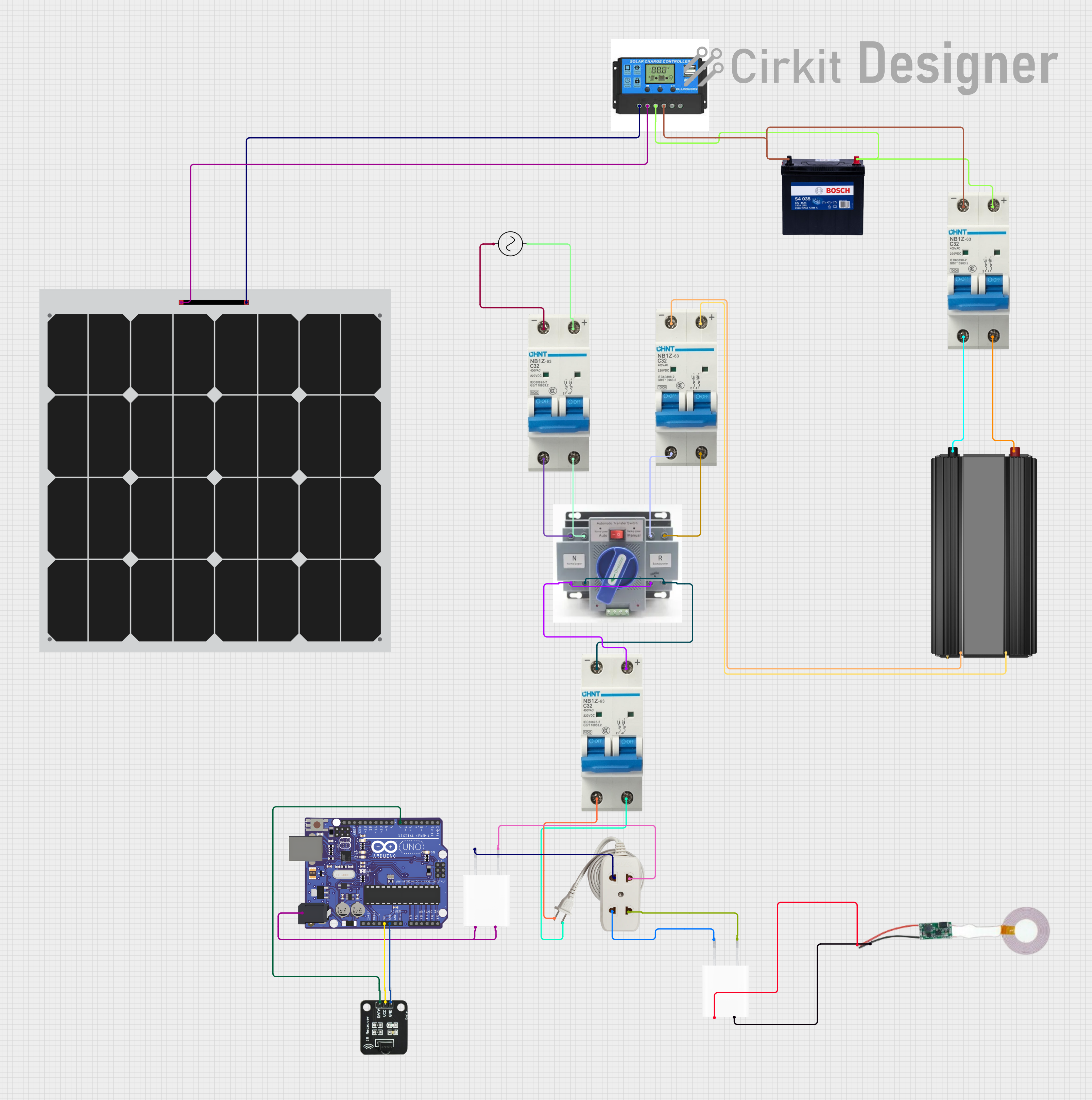
Solar-Powered Energy System with Arduino-Controlled ATS and IR Interface

Solar-Powered Battery System with Backup AC Supply and Arduino Control
Summary
This circuit is designed to create a solar-powered battery system with a backup AC supply, featuring an Arduino UNO for control purposes. The system includes a solar panel connected to a charge controller, which manages the charging of a 12V 200Ah battery. The battery's output is regulated through circuit breakers before being converted to AC by a power inverter. An Automatic Transfer Switch (ATS) is used to switch between solar power and an AC supply as needed. Additionally, the system includes a 5V adapter for powering low-voltage components, such as an IR receiver and a wireless charging module receiver. The Arduino UNO is integrated for monitoring and control, interfacing with the IR receiver for potential remote operation.
Component List
Power Components
- 12V 200Ah Battery: A high-capacity battery for energy storage.
- Solar Panel: A photovoltaic panel for converting solar energy into electrical power.
- Charge Controller: Manages the charging of the battery from the solar panel and provides load output.
- Power Inverter: Converts the battery's DC power into AC power for use with AC appliances.
- ATS (Automatic Transfer Switch): Automatically switches between solar power and AC supply.
- AC Supply: An alternative power source when solar energy is insufficient.
- 5V Adapter: Steps down AC power to 5V DC for low-voltage electronics.
Control and Monitoring Components
- Arduino UNO: A microcontroller board for implementing control logic and interfacing with sensors.
- IR Receiver: Receives infrared signals for remote control functionality.
Safety and Connectivity Components
- Circuit Breaker: Provides overcurrent protection for various parts of the circuit.
- Wireless Charging Module Receiver: Receives power wirelessly for charging or powering devices.
- Extension: Represents additional wiring or connectivity options within the system.
Wiring Details
12V 200Ah Battery
- GND connected to Charge Controller Battery Negative and Circuit Breaker (-).
- 12V connected to Charge Controller Battery Positive and Circuit Breaker (+).
Solar Panel
- + connected to Charge Controller Solar Positive.
- - connected to Charge Controller Solar Negative.
Charge Controller
- Solar Positive connected to Solar Panel (+).
- Solar Negative connected to Solar Panel (-).
- Battery Positive connected to 12V 200Ah Battery (12V) and Circuit Breaker (+).
- Battery Negative connected to 12V 200Ah Battery (GND) and Circuit Breaker (-).
- Load Positive and Load Negative not detailed in the net list.
Power Inverter
- - connected to Circuit Breaker (-).
- + connected to Circuit Breaker (+).
ATS (Automatic Transfer Switch)
- + connected to Circuit Breaker (-) from AC Supply and Circuit Breaker (+) from Power Inverter.
- - connected to Circuit Breaker (+) from AC Supply and Circuit Breaker (-) from Power Inverter.
AC Supply
- +ve connected to Circuit Breaker (+).
- -ve connected to Circuit Breaker (-).
5V Adapter
- AC In 1 and AC In 2 connected to Extension.
- 5V connected to Wireless Charging Module Receiver Positive and Arduino UNO (5V).
- GND connected to Wireless Charging Module Receiver Negative and Arduino UNO (GND).
Extension
- Represents connections to 5V Adapter AC In 1 and AC In 2.
Arduino UNO
- 5V and GND connected to 5V Adapter.
- D7 connected to IR Receiver DATA.
IR Receiver
- DATA connected to Arduino UNO (D7).
- VCC connected to Arduino UNO (5V).
- GND connected to Arduino UNO (GND).
Wireless Charging Module Receiver
- Positive connected to 5V Adapter (5V).
- Negative connected to 5V Adapter (GND).
Documented Code
No code was provided for the microcontroller(s) in the circuit. If code is available, it should be documented here with explanations for each function and routine, including setup and loop functions for Arduino-based systems.