
ESP32-Controlled Stepper Motor and Servo System with Power Management
View and Edit Project In Cirkit Designer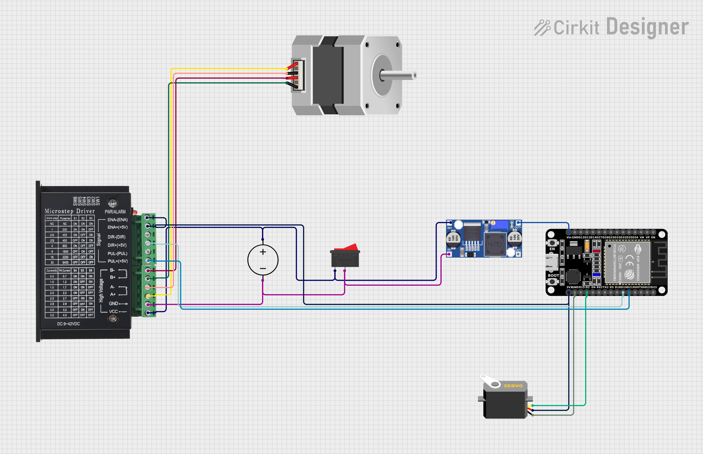
Circuit Documentation
Summary
The circuit in question is designed to control a bipolar stepper motor using an ESP32 microcontroller and a tb6600 micro stepping motor driver. A DC power source is regulated by a buck converter to supply the appropriate voltage levels to the ESP32 and the motor driver. A rocker switch is included to control the power flow to the motor driver. Additionally, a servo motor is controlled directly by the ESP32. The circuit is intended for applications where precise motor control is required, such as in robotics or automation systems.
Component List
Rocker Switch
- Description: A switch to control the connection of the power supply to the circuit.
- Pins: 2 (1, 2)
DC Power Source
- Description: Provides the input voltage to the circuit.
- Pins: 2 (Ground, Positive)
ESP32 (30 pin)
- Description: A microcontroller with Wi-Fi and Bluetooth capabilities, used for controlling the motors.
- Pins: 29 (EN, VP, VN, D34, D35, D32, D33, D25, D26, D27, D14, D12, D13, GND, Vin, D23, D22, TX0, RX0, D21, D19, D18, D5, TX2, RX2, D4, D2, D15, 3V3)
Buck Converter
- Description: Steps down the voltage from the power source to a level suitable for the ESP32 and motor driver.
- Pins: 4 (IN+, IN-, OUT+, OUT-)
tb6600 Micro Stepping Motor Driver
- Description: Drives the stepper motor based on signals from the ESP32.
- Pins: 12 (ENA-, ENA+, DIR-, DIR+, PUL-, PUL+, B-, B+, A-, A+, GND, VCC)
Stepper Motor (Bipolar)
- Description: A bipolar stepper motor controlled by the tb6600 driver.
- Pins: 4 (A, B, C, D)
Servo
- Description: A servo motor controlled directly by the ESP32.
- Pins: 3 (gnd, vcc, pulse)
Wiring Details
Rocker Switch
- Pin 1: Connected to the positive pin of the DC Power Source and the IN+ pin of the Buck Converter.
- Pin 2: Connected to the ground pin of the DC Power Source and the IN- pin of the Buck Converter.
DC Power Source
- Positive: Connected to the Rocker Switch and the Buck Converter.
- Ground: Connected to the Rocker Switch and the Buck Converter.
ESP32 (30 pin)
- Vin: Connected to the OUT+ pin of the Buck Converter.
- GND: Common ground with the Servo and tb6600 Motor Driver.
- D21: Connected to the PUL+ pin of the tb6600 Motor Driver.
- D19: Connected to the DIR+ pin of the tb6600 Motor Driver.
- D2: Connected to the pulse pin of the Servo.
- 3V3: Connected to the vcc pin of the Servo and the ENA- and ENA+ pins of the tb6600 Motor Driver.
Buck Converter
- IN+: Connected to the positive pin of the DC Power Source and the Rocker Switch.
- IN-: Connected to the ground pin of the DC Power Source and the Rocker Switch.
- OUT+: Connected to the Vin pin of the ESP32.
- OUT-: Common ground with the ESP32.
tb6600 Micro Stepping Motor Driver
- VCC: Connected to the positive pin of the DC Power Source through the Rocker Switch.
- GND: Common ground with the ESP32.
- PUL+: Connected to the D21 pin of the ESP32.
- DIR+: Connected to the D19 pin of the ESP32.
- ENA-: Connected to the 3V3 pin of the ESP32.
- ENA+: Connected to the 3V3 pin of the ESP32.
- B-: Connected to the B pin of the Stepper Motor.
- B+: Connected to the D pin of the Stepper Motor.
- A-: Connected to the C pin of the Stepper Motor.
- A+: Connected to the A pin of the Stepper Motor.
Stepper Motor (Bipolar)
- A: Connected to the A+ pin of the tb6600 Motor Driver.
- B: Connected to the B- pin of the tb6600 Motor Driver.
- C: Connected to the A- pin of the tb6600 Motor Driver.
- D: Connected to the B+ pin of the tb6600 Motor Driver.
Servo
- gnd: Common ground with the ESP32.
- vcc: Connected to the 3V3 pin of the ESP32.
- pulse: Connected to the D2 pin of the ESP32.
Documented Code
No code was provided for the microcontroller. The documentation of the code would typically include a description of the functionality, setup, and loop routines, as well as any functions or libraries used to control the motors. Since no code is available, this section cannot be completed. If code becomes available, it should be documented here with comments explaining the purpose and functionality of each section of the code.