
Arduino UNO-Based Timer with Rotary Encoder and LCD Display for Relay Control
View and Edit Project In Cirkit Designer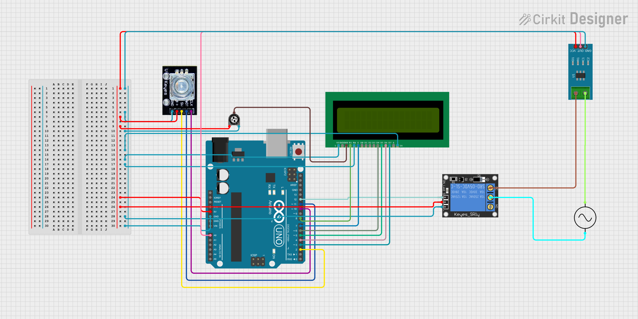
Circuit Documentation
Summary
This circuit is designed to control a relay using an Arduino UNO, a rotary encoder, and a 16x2 LCD display. The circuit also includes a current sensor and a trimmer potentiometer for additional functionality. The Arduino UNO is programmed to read inputs from the rotary encoder and display the information on the LCD. The relay is controlled based on the inputs and the current sensor readings.
Component List
Arduino UNO
- Description: A microcontroller board based on the ATmega328P.
- Pins: UNUSED, IOREF, Reset, 3.3V, 5V, GND, Vin, A0, A1, A2, A3, A4, A5, SCL, SDA, AREF, D13, D12, D11, D10, D9, D8, D7, D6, D5, D4, D3, D2, D1, D0
Rotary Encoder
- Description: A device that converts the angular position or motion of a shaft to an analog or digital code.
- Pins: clk, dt, sw, gnd, +
16x2 LCD
- Description: A liquid crystal display that can display 16 characters per line and has 2 lines.
- Pins: VSS, VDD, V0, RS, RW, E, D1, D0, D2, D3, D4, D6, D5, D7, A, K
1-Channel Relay (5V 10A)
- Description: A relay module that can control high voltage devices with a low voltage signal.
- Pins: NC, signal, C, power, NO, ground
Trimmer Potentiometer
- Description: A variable resistor used to adjust the level of voltage in a circuit.
- Pins: leg1, wiper, leg2
- Properties: Resistance: 10000 Ohms
AC Supply
- Description: A power supply that provides alternating current.
- Pins: +ve, -ve
Current Sensor 5A
- Description: A sensor that measures the current flowing through a circuit.
- Pins: 1, 2, GND, OUT, VCC
Wiring Details
Arduino UNO
5V connected to:
- Current Sensor 5A (VCC)
- Rotary Encoder (+)
- Trimmer Potentiometer (leg1)
- 1-Channel Relay (power)
GND connected to:
- Current Sensor 5A (GND)
- Rotary Encoder (gnd)
- Trimmer Potentiometer (leg2)
- 16x2 LCD (K, VSS, RW)
- 1-Channel Relay (ground)
A0 connected to:
- Current Sensor 5A (OUT)
D12 connected to:
- 1-Channel Relay (signal)
D11 connected to:
- Rotary Encoder (dt)
D10 connected to:
- Rotary Encoder (clk)
D8 connected to:
- 16x2 LCD (RS)
D7 connected to:
- 16x2 LCD (E)
D6 connected to:
- 16x2 LCD (D4)
D5 connected to:
- 16x2 LCD (D5)
D4 connected to:
- 16x2 LCD (D6)
D3 connected to:
- 16x2 LCD (D7)
D2 connected to:
- Rotary Encoder (sw)
Rotary Encoder
+ connected to:
- Arduino UNO (5V)
gnd connected to:
- Arduino UNO (GND)
clk connected to:
- Arduino UNO (D10)
dt connected to:
- Arduino UNO (D11)
sw connected to:
- Arduino UNO (D2)
16x2 LCD
VSS connected to:
- Arduino UNO (GND)
VDD connected to:
- Trimmer Potentiometer (wiper)
V0 connected to:
- Trimmer Potentiometer (wiper)
RS connected to:
- Arduino UNO (D8)
RW connected to:
- Arduino UNO (GND)
E connected to:
- Arduino UNO (D7)
D4 connected to:
- Arduino UNO (D6)
D5 connected to:
- Arduino UNO (D5)
D6 connected to:
- Arduino UNO (D4)
D7 connected to:
- Arduino UNO (D3)
K connected to:
- Arduino UNO (GND)
1-Channel Relay (5V 10A)
power connected to:
- Arduino UNO (5V)
ground connected to:
- Arduino UNO (GND)
signal connected to:
- Arduino UNO (D12)
NC connected to:
- Current Sensor 5A (1)
C connected to:
- AC Supply (+ve)
Trimmer Potentiometer
leg1 connected to:
- Arduino UNO (5V)
leg2 connected to:
- Arduino UNO (GND)
wiper connected to:
- 16x2 LCD (V0)
AC Supply
+ve connected to:
- 1-Channel Relay (C)
-ve connected to:
- Current Sensor 5A (2)
Current Sensor 5A
VCC connected to:
- Arduino UNO (5V)
GND connected to:
- Arduino UNO (GND)
OUT connected to:
- Arduino UNO (A0)
1 connected to:
- 1-Channel Relay (NC)
2 connected to:
- AC Supply (-ve)
Code Documentation
#include <LiquidCrystal.h>
#include <EEPROM.h>

LiquidCrystal lcd(8, 7, 6, 5, 4, 3);

#define outputA 10 // clk pin of rotary encoder
#define outputB 11 // dt pin of rotary encoder
#define button 2   // sw pin of rotary encoder
#define led 13     // status led
#define relay 12   // in1 of relay

int count = 1;
int current_state;
int previous_state;
int hh = 0;
int mm = 0;
int ss = 0;
int h = 0;
int m = 0;
int s = 0;
int ledToggle;
int previousState = HIGH;
unsigned int previousPress;
volatile int buttonFlag;
int buttonDebounce = 20;

void setup() {
  lcd.begin(16, 2);
  pinMode(outputA, INPUT);
  pinMode(outputB, INPUT);
  pinMode(button, INPUT_PULLUP);
  pinMode(led, OUTPUT);
  pinMode(relay, OUTPUT);
  digitalWrite(relay, HIGH);
  attachInterrupt(digitalPinToInterrupt(2), button_ISR, CHANGE);
  Serial.begin(9600);
  previous_state = digitalRead(outputA);

  if (EEPROM.read(0) != 0 || EEPROM.read(1) != 0 || EEPROM.read(2) != 0) {
    lcd.setCursor(0, 0);
    lcd.print("Load Preset ?");
    lcd.print(" ");
    lcd.setCursor(0, 1);
    lcd.print("      <NO>      ");
    int temp = 5;
    while (temp > 0 && ledToggle == 0) {
      lcd.setCursor(14, 0);
      lcd.print(temp);
      temp--;
      delay(1000);
    }
    if (temp == 0 && ledToggle == 0) {
      hh = EEPROM.read(0);
      mm = EEPROM.read(1);
      ss = EEPROM.read(2);
      timer();
    } else {
      EEPROM.write(0, 0);
      EEPROM.write(1, 0);
      EEPROM.write(2, 0);
      ledToggle = 0;
    }
  }
  lcd.clear();
  lcd.setCursor(0, 0);
  lcd.print(" HH  MM  SS  OK ");
  lcd.setCursor(0, 1);
  lcd.print(" 0   0   0      ");
}

void loop() {
  encoder();
  if (count == 1) {
    lcd.setCursor(0, 0);
    lcd.print("<HH> MM  SS  OK ");
    while (count == 1) {
      encoder();
      if (ledToggle) {
        h = 1;
        m = 0;
        s = 0;
        lcd.setCursor(0, 0);
        lcd.print(" HH  MM  SS  OK ");
        lcd.setCursor(1, 1);
        lcd.print(hh);
        lcd