
Arduino UNO Stepper Motor Controller with Phototransistor and Pushbutton Inputs
View and Edit Project In Cirkit Designer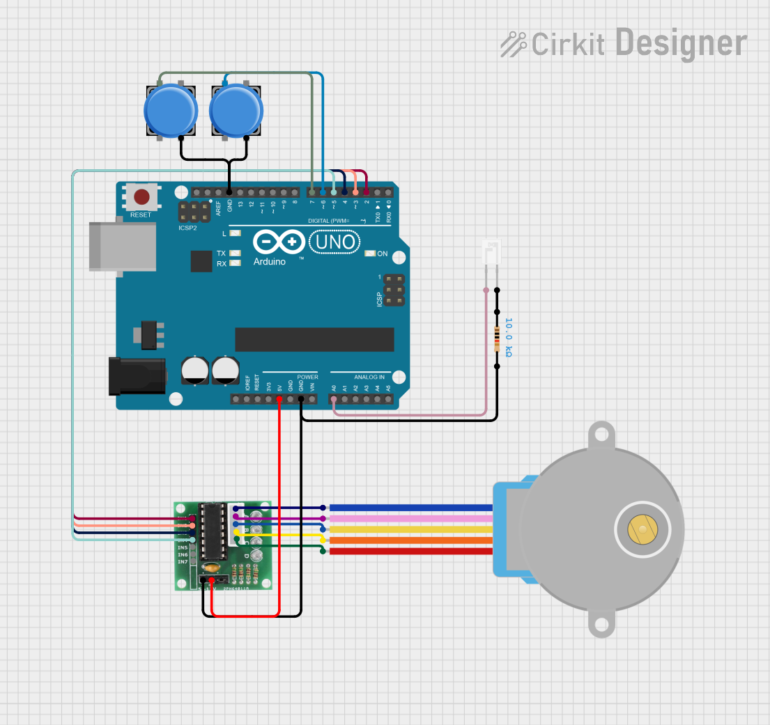
Circuit Documentation
Summary
This circuit involves an Arduino UNO microcontroller, a phototransistor, a stepper motor, pushbuttons, a ULN 2003 driver, and a resistor. The Arduino UNO reads input from the phototransistor and pushbuttons, and controls the stepper motor through the ULN 2003 driver. The phototransistor measures light intensity, and the pushbuttons allow for manual control of the stepper motor's rotation.
Component List
Arduino UNO
- Description: A microcontroller board based on the ATmega328P.
- Pins: UNUSED, IOREF, Reset, 3.3V, 5V, GND, Vin, A0, A1, A2, A3, A4, A5, SCL, SDA, AREF, D13, D12, D11, D10, D9, D8, D7, D6, D5, D4, D3, D2, D1, D0
Phototransistor
- Description: A light-sensitive transistor.
- Pins: C (Collector), E (Emitter)
28BYJ-48 Stepper Motor
- Description: A 5V stepper motor.
- Pins: BLUE, PINK, YELLOW, ORANGE, RED
Pushbutton
- Description: A simple pushbutton switch.
- Pins: Pin 2, Pin 1, Pin 3, Pin 4
ULN 2003
- Description: A high-voltage, high-current Darlington transistor array.
- Pins: IN1, IN2, IN3, IN4, IN5, IN6, IN7, GND, +, COIL1, COIL2, COIL3, COIL4, COIL5
Resistor
- Description: A 10k Ohm resistor.
- Pins: pin1, pin2
- Properties: Resistance = 10k Ohms
Wiring Details
Arduino UNO
- 5V connected to + of ULN 2003
- GND connected to GND of ULN 2003 and pin2 of Resistor
- A0 connected to E of Phototransistor
- D7 connected to Pin 1 of Pushbutton 1
- D6 connected to Pin 1 of Pushbutton 2
- D5 connected to IN4 of ULN 2003
- D4 connected to IN3 of ULN 2003
- D3 connected to IN2 of ULN 2003
- D2 connected to IN1 of ULN 2003
Phototransistor
- C connected to pin1 of Resistor
- E connected to A0 of Arduino UNO
28BYJ-48 Stepper Motor
- BLUE connected to COIL1 of ULN 2003
- PINK connected to COIL2 of ULN 2003
- YELLOW connected to COIL3 of ULN 2003
- ORANGE connected to COIL4 of ULN 2003
- RED connected to COIL5 of ULN 2003
Pushbutton 1
- Pin 4 connected to GND of Arduino UNO
- Pin 1 connected to D7 of Arduino UNO
Pushbutton 2
- Pin 4 connected to GND of Arduino UNO
- Pin 1 connected to D6 of Arduino UNO
ULN 2003
- + connected to 5V of Arduino UNO
- GND connected to GND of Arduino UNO and pin2 of Resistor
- IN1 connected to D2 of Arduino UNO
- IN2 connected to D3 of Arduino UNO
- IN3 connected to D4 of Arduino UNO
- IN4 connected to D5 of Arduino UNO
- COIL1 connected to BLUE of Stepper Motor
- COIL2 connected to PINK of Stepper Motor
- COIL3 connected to YELLOW of Stepper Motor
- COIL4 connected to ORANGE of Stepper Motor
- COIL5 connected to RED of Stepper Motor
Resistor
- pin1 connected to C of Phototransistor
- pin2 connected to GND of Arduino UNO and GND of ULN 2003
Code Documentation
#include <Stepper.h>

// Define the number of steps per revolution for the stepper motor
#define STEPS_PER_REV 2048

// Define pin connections
const int motorPin1 = 2; // IN1 on ULN2003 to D2 on Arduino
const int motorPin2 = 3; // IN2 on ULN2003 to D3 on Arduino
const int motorPin3 = 4; // IN3 on ULN2003 to D4 on Arduino
const int motorPin4 = 5; // IN4 on ULN2003 to D5 on Arduino
const int button1Pin = 6; // Pushbutton 1 to D6 on Arduino
const int button2Pin = 7; // Pushbutton 2 to D7 on Arduino
const int photoPin = A0; // Phototransistor to A0 on Arduino

// Initialize the stepper library
Stepper stepper(STEPS_PER_REV, motorPin1, motorPin3, motorPin2, motorPin4);

void setup() {
  // Set up the motor pins as outputs
  pinMode(motorPin1, OUTPUT);
  pinMode(motorPin2, OUTPUT);
  pinMode(motorPin3, OUTPUT);
  pinMode(motorPin4, OUTPUT);

  // Set up the button pins as inputs
  pinMode(button1Pin, INPUT);
  pinMode(button2Pin, INPUT);

  // Initialize serial communication for debugging
  Serial.begin(9600);
}

void loop() {
  // Read the state of the pushbuttons
  int button1State = digitalRead(button1Pin);
  int button2State = digitalRead(button2Pin);

  // Read the value from the phototransistor
  int photoValue = analogRead(photoPin);

  // Print the phototransistor value to the serial monitor
  Serial.print("Light Intensity: ");
  Serial.println(photoValue);

  // Control the stepper motor based on button states
  if (button1State == HIGH) {
    // Rotate the motor clockwise
    stepper.step(1);
  } else if (button2State == HIGH) {
    // Rotate the motor counterclockwise
    stepper.step(-1);
  }

  // Add a small delay to debounce the buttons
  delay(50);
}
This code initializes the stepper motor and sets up the pushbuttons and phototransistor. In the main loop, it reads the state of the pushbuttons and the value from the phototransistor, printing the light intensity to the serial monitor. Depending on the state of the pushbuttons, it rotates the stepper motor clockwise or counterclockwise.