ESP32-Controlled Ultrasonic Distance Measurement with Relay Switching and I2C LCD Display
Circuit Documentation
Summary
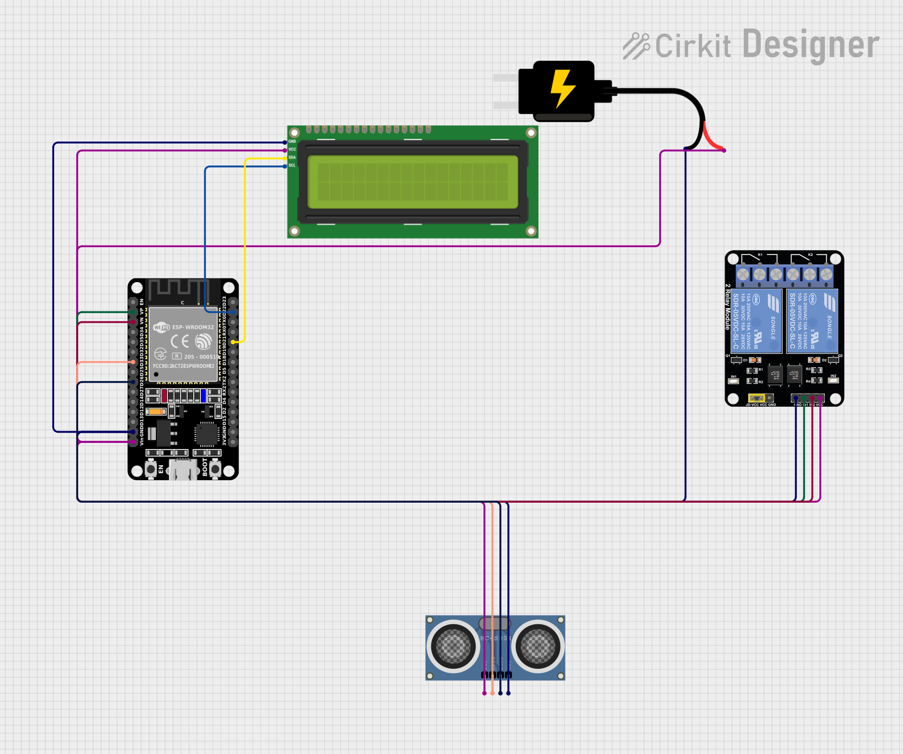
This circuit is designed to interface an ESP32 microcontroller with several peripherals: an I2C LCD 16x2 screen, an HC-SR04 Ultrasonic Distance Sensor, and a 2-Channel Relay Module. The ESP32 is responsible for measuring distance using the ultrasonic sensor, displaying the measurement on the LCD screen, and controlling the relay module based on the distance detected. The relay module can switch external devices or circuits on or off depending on the sensor's output.
Component List
ESP32 (30 pin)
- Description: A microcontroller with Wi-Fi and Bluetooth capabilities, featuring a wide range of GPIO pins.
- Purpose: Acts as the central processing unit of the circuit, interfacing with the sensor, display, and relay module.
I2C LCD 16x2 Screen
- Description: A liquid crystal display capable of showing 16 characters per line, with 2 lines. It uses the I2C communication protocol.
- Purpose: Displays the distance measurements from the ultrasonic sensor.
DC Source 5V
- Description: A power supply module that provides a regulated 5V output.
- Purpose: Powers the ESP32, LCD screen, relay module, and ultrasonic sensor.
Relay Module 2 Channel
- Description: An electronic switch that can control the high power or high voltage load with low voltage signals.
- Purpose: Switches external devices based on the ESP32's commands.
HC-SR04 Ultrasonic Distance Sensor (Wokwi Compatible)
- Description: A sensor that measures distance by emitting ultrasonic waves and measuring the time taken for the echo to return.
- Purpose: Measures the distance to an object and provides this information to the ESP32.
Wiring Details
ESP32 (30 pin)
- EN: Not connected
- VP: Connected to Relay Module IN1
- VN: Connected to Relay Module IN2
- D34-D15, 3V3: Not connected
- D33: Connected to Ultrasonic Sensor TRIG
- D26: Connected to Ultrasonic Sensor ECHO
- D22: Connected to LCD SCL
- D21: Connected to LCD SDA
- GND: Common ground with all components
- Vin: Connected to the 5V rail from the DC Source
I2C LCD 16x2 Screen
- SCL: Connected to ESP32 D22
- SDA: Connected to ESP32 D21
- VCC (5V): Connected to the 5V rail from the DC Source
- GND: Common ground with all components
DC Source 5V
- VCC: Connected to ESP32 Vin, LCD VCC (5V), Relay Module VCC, and Ultrasonic Sensor VCC
- GND: Common ground with all components
Relay Module 2 Channel
- IN1: Connected to ESP32 VP
- IN2: Connected to ESP32 VN
- VCC: Connected to the 5V rail from the DC Source
- GND: Common ground with all components
- NC1, COM, NO1, NC2, NO2: Not connected or used for external connections
HC-SR04 Ultrasonic Distance Sensor (Wokwi Compatible)
- TRIG: Connected to ESP32 D33
- ECHO: Connected to ESP32 D26
- VCC: Connected to the 5V rail from the DC Source
- GND: Common ground with all components
Documented Code
/*
 * This Arduino Sketch interfaces an ESP32 with an I2C LCD 16x2 screen,
 * an HC-SR04 Ultrasonic Distance Sensor, and a 2-Channel Relay Module.
 * The ESP32 displays distance measurements on the LCD screen and controls
 * the relay based on the distance measured by the ultrasonic sensor.
 * Connections:
 * - ESP32 GND to LCD GND, Relay GND, Ultrasonic Sensor GND
 * - ESP32 Vin to LCD VCC (5V), Relay VCC, Ultrasonic Sensor VCC
 * - ESP32 D22 to LCD SCL
 * - ESP32 D21 to LCD SDA
 * - ESP32 D33 to Ultrasonic Sensor TRIG
 * - ESP32 D26 to Ultrasonic Sensor ECHO
 * - ESP32 VP to Relay IN1
 * - ESP32 VN to Relay IN2
 */

#include <Wire.h>
#include <LiquidCrystal_I2C.h>

#define TRIG_PIN 33
#define ECHO_PIN 26
#define RELAY1_PIN 36 // VP
#define RELAY2_PIN 39 // VN

LiquidCrystal_I2C lcd(0x27, 16, 2);

void setup() {
  Serial.begin(115200);
  lcd.init();
  lcd.backlight();
  lcd.print("Initializing...");
  pinMode(TRIG_PIN, OUTPUT);
  pinMode(ECHO_PIN, INPUT);
  pinMode(RELAY1_PIN, OUTPUT);
  pinMode(RELAY2_PIN, OUTPUT);
  digitalWrite(RELAY1_PIN, LOW);
  digitalWrite(RELAY2_PIN, LOW);
  delay(2000);
  lcd.clear();
}

void loop() {
  long duration, distance;
  digitalWrite(TRIG_PIN, LOW);
  delayMicroseconds(2);
  digitalWrite(TRIG_PIN, HIGH);
  delayMicroseconds(10);
  digitalWrite(TRIG_PIN, LOW);
  duration = pulseIn(ECHO_PIN, HIGH);
  distance = (duration / 2) / 29.1;
  lcd.clear();
  lcd.setCursor(0, 0);
  lcd.print("Distance: ");
  lcd.print(distance);
  lcd.print(" cm");
  if (distance < 10) {
    digitalWrite(RELAY1_PIN, HIGH);
    digitalWrite(RELAY2_PIN, LOW);
  } else if (distance < 20) {
    digitalWrite(RELAY1_PIN, LOW);
    digitalWrite(RELAY2_PIN, HIGH);
  } else {
    digitalWrite(RELAY1_PIN, LOW);
    digitalWrite(RELAY2_PIN, LOW);
  }
  delay(1000);
}
This code initializes the connected devices and enters a loop where it measures distance using the ultrasonic sensor, displays the result on the LCD, and controls the relay module based on the measured distance. The relay logic is set to activate one relay if the distance is less than 10 cm, another if the distance is between 10 and 20 cm, and turn off both if the distance is greater than 20 cm.