Cirkit Designer
Your all-in-one circuit design IDE
Home /
Project Documentation
Arduino UNO-Based Automated Irrigation and Ventilation System with IR Sensors and LCD Display
Circuit Documentation
Summary
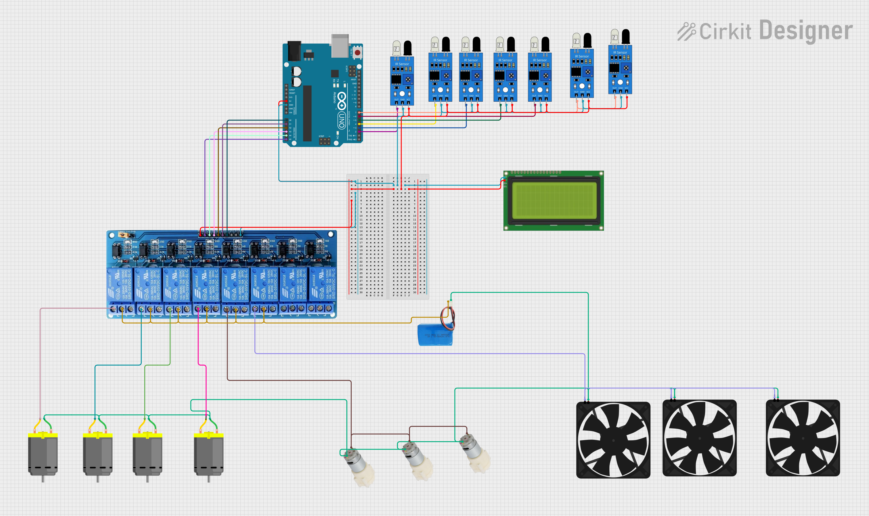
This circuit involves an Arduino UNO microcontroller interfacing with multiple IR sensors, a 20x4 I2C LCD, an 8-channel relay module, DC motors, water pumps, and fans. The Arduino UNO reads inputs from the IR sensors and controls the relay module, which in turn controls the DC motors, water pumps, and fans. The LCD displays relevant information.
Component List
Arduino UNO
- Description: Microcontroller board based on the ATmega328P.
- Pins: UNUSED, IOREF, Reset, 3.3V, 5V, GND, Vin, A0, A1, A2, A3, A4, A5, SCL, SDA, AREF, D13, D12, D11, D10, D9, D8, D7, D6, D5, D4, D3, D2, D1, D0
IR Sensor
- Description: Infrared sensor for object detection.
- Pins: out, gnd, vcc
LCD 20x4 I2C
- Description: 20x4 character LCD with I2C interface.
- Pins: GND, 5v, SCA, SCL
5V 8-Channel Relay
- Description: Relay module for controlling high-power devices.
- Pins: GND, IN1, IN2, IN3, IN4, IN5, IN6, IN7, IN8, VCC, NC, C, NO
DC Motor
- Description: Direct current motor.
- Pins: pin 1, pin 2
Water Pump 12V
- Description: 12V water pump.
- Pins: +, -
Fan
- Description: Cooling fan.
- Pins: GND, 5V
5V Battery
- Description: Power supply.
- Pins: positive, negative
Wiring Details
Arduino UNO
- GND: Connected to GND of all IR sensors, LCD, and relay module.
- 5V: Connected to VCC of all IR sensors, LCD, and relay module.
- A0: Connected to IN3 of the relay module.
- A1: Connected to IN4 of the relay module.
- A2: Connected to IN5 of the relay module.
- A3: Connected to IN6 of the relay module.
- A4: Connected to IN7 of the relay module.
- A5: Connected to IN8 of the relay module.
- D2: Connected to out of one IR sensor.
- D3: Connected to out of one IR sensor.
- D4: Connected to out of one IR sensor.
- D5: Connected to out of one IR sensor.
- D6: Connected to out of one IR sensor.
- D7: Connected to out of two IR sensors.
IR Sensor
- gnd: Connected to GND of Arduino UNO.
- vcc: Connected to 5V of Arduino UNO.
- out: Connected to digital pins D2, D3, D4, D5, D6, and D7 of Arduino UNO.
LCD 20x4 I2C
- GND: Connected to GND of Arduino UNO.
- 5v: Connected to 5V of Arduino UNO.
- SCA: Not connected in the provided net list.
- SCL: Not connected in the provided net list.
5V 8-Channel Relay
- GND: Connected to GND of Arduino UNO.
- VCC: Connected to 5V of Arduino UNO.
- IN3: Connected to A0 of Arduino UNO.
- IN4: Connected to A1 of Arduino UNO.
- IN5: Connected to A2 of Arduino UNO.
- IN6: Connected to A3 of Arduino UNO.
- IN7: Connected to A4 of Arduino UNO.
- IN8: Connected to A5 of Arduino UNO.
- NO: Connected to GND of all fans, negative of all water pumps, and pin 2 of all DC motors.
- C: Connected to negative of 5V battery.
DC Motor
- pin 1: Connected to positive of 5V battery.
- pin 2: Connected to NO of relay module.
Water Pump 12V
- +: Connected to positive of 5V battery.
- -: Connected to NO of relay module.
Fan
- GND: Connected to NO of relay module.
- 5V: Connected to positive of 5V battery.
5V Battery
- positive: Connected to pin 1 of all DC motors, positive of all water pumps, and 5V of all fans.
- negative: Connected to C of relay module.
Code Documentation
Arduino UNO Code
void setup() {
  // put your setup code here, to run once:

}

void loop() {
  // put your main code here, to run repeatedly:

}
This code is a basic template for the Arduino UNO. The setup() function is used to initialize any settings or configurations, and the loop() function contains the main logic that runs repeatedly. Currently, both functions are empty and need to be filled with the appropriate logic for the circuit's operation.