
ESP8266 and Arduino Uno Health Monitor with Wi-Fi and Battery-Powered Features
View and Edit Project In Cirkit Designer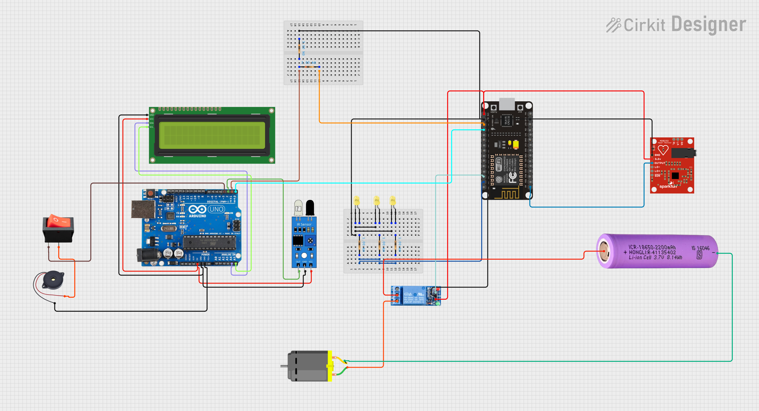
Circuit Documentation
Summary
This circuit is a health monitoring system that uses an ESP8266 NodeMCU and an Arduino Uno R3 to monitor a patient's presence on a bed using an IR sensor. The system also includes a heart rate monitor, a relay to control a DC motor, and a buzzer for alerts. The status is displayed on a 16x2 I2C LCD.
Component List
ESP8266 NodeMCU
- Description: A low-cost Wi-Fi microcontroller.
- Pins: D0, D1, D2, D3, D4, 3V3, GND, D5, D6, D7, D8, RX, TX, A0, RSV, SD3, SD2, SD1, CMD, SD0, CLK, EN, RST, VIN
1 Channel Relay 5V
- Description: A relay module to control high voltage devices.
- Pins: VCC, GND, IN, NC, COM, NO
AD8232 Heart Rate Monitor
- Description: A heart rate monitor sensor.
- Pins: GND, 3.3v, OUTPUT, LO-, LO+, SDN, RA, LA, RL
IR Sensor
- Description: An infrared sensor to detect presence.
- Pins: out, gnd, vcc
Buzzer
- Description: A simple buzzer for audio alerts.
- Pins: GND, IN
16x2 I2C LCD
- Description: A 16x2 character LCD with I2C interface.
- Pins: GND, VCC, SDA, SCL
Arduino Uno R3
- Description: A popular microcontroller board.
- Pins: D8, D9, D10, D11, D12, D13, GND, AREF, SDA, SCL, D0/RX, D1/Tx, D2, D3, D4, D5, 6, D7, A5/SCL, A4/SDA, A3, A2, A1, A0, Vin, 5V, 3.3V, RESET, IOREF, NONE, USB Jack, Power Jack
Battery 18650
- Description: A rechargeable lithium-ion battery.
- Pins: +, -
LED: Two Pin (yellow)
- Description: A yellow LED.
- Pins: cathode, anode
Resistor
- Description: A resistor with various resistance values.
- Pins: pin1, pin2
- Properties: 1000 Ohms, 2000 Ohms, 3000 Ohms
DC Motor
- Description: A simple DC motor.
- Pins: pin 1, pin 2
Rocker Switch
- Description: A simple on/off switch.
- Pins: output, input
Wiring Details
ESP8266 NodeMCU
- GND: Connected to the cathode of all yellow LEDs and the GND of the heart rate monitor and relay.
- D1: Connected to pin2 of three 1000 Ohm resistors.
- D2: Connected to the IN pin of the relay.
- RX: Connected to D0/RX of the Arduino Uno.
- TX: Connected to pin2 of a 2000 Ohm resistor.
- 3V3: Connected to the VCC of the relay and the 3.3v of the heart rate monitor.
- A0: Connected to the OUTPUT of the heart rate monitor.
1 Channel Relay 5V
- IN: Connected to D2 of the ESP8266 NodeMCU.
- VCC: Connected to 3V3 of the ESP8266 NodeMCU.
- GND: Connected to GND of the ESP8266 NodeMCU.
- COM: Connected to the positive terminal of the 18650 battery.
- NO: Connected to pin 1 of the DC motor.
AD8232 Heart Rate Monitor
- GND: Connected to GND of the ESP8266 NodeMCU.
- 3.3v: Connected to 3V3 of the ESP8266 NodeMCU.
- OUTPUT: Connected to A0 of the ESP8266 NodeMCU.
IR Sensor
- out: Connected to D2 of the Arduino Uno.
- gnd: Connected to GND of the Arduino Uno.
- vcc: Connected to 5V of the Arduino Uno.
Buzzer
- GND: Connected to GND of the Arduino Uno.
- IN: Connected to the output of the rocker switch.
16x2 I2C LCD
- GND: Connected to GND of the Arduino Uno.
- VCC: Connected to 5V of the Arduino Uno.
- SDA: Connected to A4/SDA of the Arduino Uno.
- SCL: Connected to A5/SCL of the Arduino Uno.
Arduino Uno R3
- D0/RX: Connected to RX of the ESP8266 NodeMCU.
- D1/Tx: Connected to pin2 of a 2000 Ohm resistor.
- D2: Connected to the out pin of the IR sensor.
- D3: Connected to the input of the rocker switch.
- GND: Connected to GND of the IR sensor, LCD, and buzzer.
- 5V: Connected to vcc of the IR sensor and LCD.
- A4/SDA: Connected to SDA of the LCD.
- A5/SCL: Connected to SCL of the LCD.
Battery 18650
- +: Connected to COM of the relay.
- -: Connected to pin 2 of the DC motor.
LED: Two Pin (yellow)
- cathode: Connected to GND of the ESP8266 NodeMCU.
- anode: Connected to pin1 of 1000 Ohm resistors.
Resistor
- pin1: Connected to the anode of yellow LEDs.
- pin2: Connected to D1 of the ESP8266 NodeMCU and D1/Tx of the Arduino Uno.
DC Motor
- pin 1: Connected to NO of the relay.
- pin 2: Connected to the negative terminal of the 18650 battery.
Rocker Switch
- output: Connected to IN of the buzzer.
- input: Connected to D3 of the Arduino Uno.
Documented Code
ESP8266 NodeMCU Code
void setup() {
  // put your setup code here, to run once:

}

void loop() {
  // put your main code here, to run repeatedly:

}
Arduino Uno R3 Code
#include <Wire.h>
#include <LiquidCrystal_I2C.h>

// Initialize the LCD with I2C address 0x27 and dimensions 16x2
LiquidCrystal_I2C lcd(0x27, 16, 2);

#define IR_PIN 2       // IR sensor input pin
#define BUZZER_PIN 3   // Buzzer output pin

void setup() {
  // Initialize the LCD
  lcd.begin();
  lcd.backlight();
  lcd.setCursor(0, 0);
  lcd.print("Health Monitor");

  // Initialize IR sensor and buzzer
  pinMode(IR_PIN, INPUT);
  pinMode(BUZZER_PIN, OUTPUT);

  // Display initial status
  lcd.setCursor(0, 1);
  lcd.print("Initializing...");
  delay(2000);
  lcd.clear();
}

void loop() {
  // Read IR sensor status
  int irStatus = digitalRead(IR_PIN);

  // Adjusted logic for active-low sensors
  if (irStatus == LOW) { // Patient detected
    lcd.setCursor(0, 0);
    lcd.print("Patient on Bed   "); // Clear extra characters
    lcd.setCursor(0, 1);
    lcd.print("Status: Safe     ");
    digitalWrite(BUZZER_PIN, LOW); // Turn off buzzer
  } else { // Patient not detected
    lcd.setCursor(0, 0);
    lcd.print("Patient not on   ");
    lcd.setCursor(0, 1);
    lcd.print("Bed! Alert!      ");
    digitalWrite(BUZZER_PIN, HIGH); // Turn on buzzer
  }

  delay(500);
}