ESP8266 NodeMCU Controlled RFID Access System with Visual and Audio Indicators
Circuit Documentation
Summary
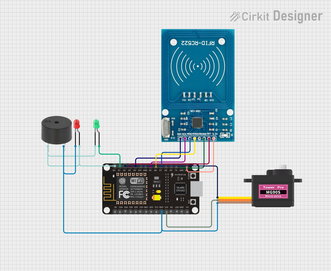
This circuit integrates an ESP8266 NodeMCU microcontroller with an RFID-RC522 reader, a buzzer, two LEDs (one red and one green), and a Servomotor MG90S. The ESP8266 NodeMCU serves as the central processing unit, controlling the RFID reader for tag detection, driving the LEDs and buzzer for user feedback, and operating the servomotor based on the RFID tags read. The circuit is designed for applications such as access control systems where RFID tags are used to trigger actions like unlocking a door or triggering an alarm.
Component List
ESP8266 NodeMCU
- Microcontroller with WiFi capability
- Pins: D0, D1, D2, D3, D4, 3V3, GND, D5, D6, D7, D8, RX, TX, A0, RSV, SD3, SD2, SD1, CMD, SD0, CLK, EN, RST, VIN
RFID-RC522
- RFID reader module for reading RFID tags
- Pins: VCC (3.3V), RST, GND, IRQ, MISO, MOSI, SCK, SDA
Buzzer
- An audible signaling device
- Pins: PIN, GND
LED: Two Pin (red)
- Red indicator LED
- Pins: cathode, anode
LED: Two Pin (green)
- Green indicator LED
- Pins: cathode, anode
Servomotor MG90S
- A small and lightweight servomotor for precise control
- Pins: SIG, VCC, GND
Wiring Details
ESP8266 NodeMCU
- D0 connected to the anode of the red LED, the PIN of the buzzer, and the cathode of the green LED
- D1 connected to the anode of the green LED
- D2 connected to the SIG pin of the Servomotor MG90S
- D3 connected to the RST pin of the RFID-RC522
- D4 connected to the SDA pin of the RFID-RC522
- D5 connected to the SCK pin of the RFID-RC522
- D6 connected to the MISO pin of the RFID-RC522
- D7 connected to the MOSI pin of the RFID-RC522
- GND connected to the GND pins of the RFID-RC522, the buzzer, the red LED, and the Servomotor MG90S
- 3V3 connected to the VCC (3.3V) pin of the RFID-RC522 and the VCC pin of the Servomotor MG90S
RFID-RC522
- VCC (3.3V) connected to 3V3 of the ESP8266 NodeMCU
- RST connected to D3 of the ESP8266 NodeMCU
- GND connected to GND of the ESP8266 NodeMCU
- MISO connected to D6 of the ESP8266 NodeMCU
- MOSI connected to D7 of the ESP8266 NodeMCU
- SCK connected to D5 of the ESP8266 NodeMCU
- SDA connected to D4 of the ESP8266 NodeMCU
Buzzer
- PIN connected to D0 of the ESP8266 NodeMCU
- GND connected to GND of the ESP8266 NodeMCU
LED: Two Pin (red)
- Anode connected to D0 of the ESP8266 NodeMCU
- Cathode connected to GND of the ESP8266 NodeMCU
LED: Two Pin (green)
- Anode connected to D1 of the ESP8266 NodeMCU
- Cathode connected to D0 of the ESP8266 NodeMCU
Servomotor MG90S
- SIG connected to D2 of the ESP8266 NodeMCU
- VCC connected to 3V3 of the ESP8266 NodeMCU
- GND connected to GND of the ESP8266 NodeMCU
Documented Code
No code has been provided for the microcontroller. The documentation of the code would typically include a description of the functionality implemented, setup and loop functions, and any functions or libraries used to control the peripherals (RFID reader, LEDs, buzzer, and servomotor). Since no code is available, this section cannot be completed.