Cirkit Designer
Your all-in-one circuit design IDE
Home /
Project Documentation
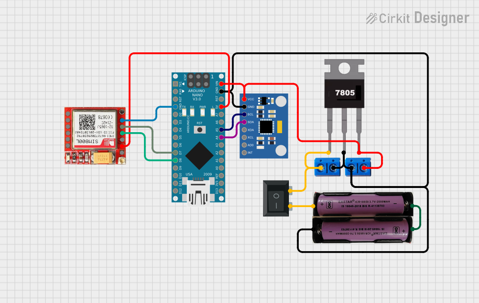
Battery-Powered Arduino Nano IoT Device with SIM800L and MPU6050
Circuit Documentation
Summary
This circuit integrates an Arduino Nano microcontroller, a SIM800L GSM module, an MPU6050 accelerometer and gyroscope, a 7805 voltage regulator, a rocker switch, and two 3.7V batteries. The circuit is designed to provide a stable 5V power supply to the components and facilitate communication between the Arduino Nano, the SIM800L module, and the MPU6050 sensor.
Component List
Arduino Nano
- Description: A compact microcontroller board based on the ATmega328P.
- Pins: D1/TX, D0/RX, RESET, GND, D2, D3, D4, D5, D6, D7, D8, D9, D10, D11/MOSI, D12/MISO, VIN, 5V, A7, A6, A5, A4, A3, A2, A1, A0, AREF, 3V3, D13/SCK
SIM800L
- Description: A GSM/GPRS module for communication over cellular networks.
- Pins: NET, VCC, RST, RXD, TXD, GND, RING, DTR, MIC+, MIC-, SPK+, SPK-
MPU6050 Accelerometer + Gyroscope (Wokwi Compatible)
- Description: A sensor module that provides accelerometer and gyroscope data.
- Pins: INT, AD0, XCL, XDA, SDA, SCL, GND, VCC
7805
- Description: A voltage regulator that outputs a stable 5V.
- Pins: Vin, Gnd, Vout
Terminal PCB 2 Pin
- Description: A terminal block for connecting wires.
- Pins: Pin A, Pin B
3.7V Battery
- Description: A rechargeable lithium-ion battery.
- Pins: +, -
Rocker Switch (SPST)
- Description: A single-pole single-throw switch.
- Pins: 1, 2
Wiring Details
Arduino Nano
- A4 connected to MPU6050 SDA
- A5 connected to MPU6050 SCL
- GND connected to Terminal PCB 2 Pin Pin B, 7805 Gnd, MPU6050 GND, SIM800L GND
- VIN connected to 7805 Vout, Terminal PCB 2 Pin Pin B
- D7 connected to SIM800L TXD
- D8 connected to SIM800L RXD
- 5V connected to SIM800L VCC
SIM800L
- GND connected to Arduino Nano GND
- TXD connected to Arduino Nano D7
- RXD connected to Arduino Nano D8
- VCC connected to Arduino Nano 5V
MPU6050 Accelerometer + Gyroscope (Wokwi Compatible)
- SDA connected to Arduino Nano A4
- SCL connected to Arduino Nano A5
- GND connected to Terminal PCB 2 Pin Pin B, 7805 Gnd, Arduino Nano GND
- VCC connected to 7805 Vout, Terminal PCB 2 Pin Pin B
7805
- Vin connected to Terminal PCB 2 Pin Pin A, Rocker Switch 1
- Gnd connected to Terminal PCB 2 Pin Pin B, Arduino Nano GND, MPU6050 GND
- Vout connected to Arduino Nano VIN, MPU6050 VCC, Terminal PCB 2 Pin Pin B
Terminal PCB 2 Pin
- Pin A connected to 7805 Vin, Rocker Switch 1
- Pin B connected to 3.7V Battery -, 7805 Gnd, Arduino Nano GND, MPU6050 GND
3.7V Battery
- + connected to Rocker Switch 2
- - connected to Terminal PCB 2 Pin Pin B
Rocker Switch (SPST)
- 1 connected to 7805 Vin, Terminal PCB 2 Pin Pin A
- 2 connected to 3.7V Battery +
Code Documentation
Arduino Nano Code
void setup() {
  // put your setup code here, to run once:

}

void loop() {
  // put your main code here, to run repeatedly:

}
This code is a basic template for the Arduino Nano. The setup() function is where you initialize your components and settings, and the loop() function is where you place the main logic that runs repeatedly.