Cirkit Designer
Your all-in-one circuit design IDE
Home /
Project Documentation
Arduino Nano-Controlled GSM Relay System
Circuit Documentation
Summary of the Circuit
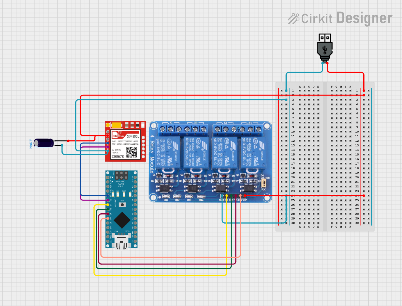
This circuit is designed to interface an Arduino Nano with a SIM800L GSM module and a 4-channel 5V relay module. It is powered by a USB power source, and an electrolytic capacitor is used for power stabilization. The Arduino Nano controls the relay module and communicates with the SIM800L module for GSM operations.
Component List
Arduino Nano
- Microcontroller board based on the ATmega328P
- It has a variety of digital and analog I/O pins
- Used for controlling the relay module and communicating with the SIM800L GSM module
Relay 4 Channel 5v
- A 4-channel relay module that operates at 5V
- Allows for controlling high power devices with Arduino's low power signals
- Each channel has a Normally Open (NO) and a Normally Closed (NC) contact
Electrolytic Capacitor
- A polarized capacitor with a specific capacitance
- Used for power supply filtering to reduce voltage spikes and noise
Sim800l
- A GSM/GPRS module that allows for cellular communication
- Can be used for sending SMS, making calls, or connecting to the internet
USB Power
- Provides power to the circuit
- Typically outputs 5V and can be sourced from a computer USB port or a USB power adapter
Wiring Details
Arduino Nano
D2connected to SIM800LRXDD3connected to SIM800LTXDD4connected to Relay ModuleIN1D5connected to Relay ModuleIN2D6connected to Relay ModuleIN3D7connected to Relay ModuleIN4
Relay 4 Channel 5v
GNDconnected to common ground netVCCconnected to common power netIN1toIN4controlled by Arduino Nano digital pinsD4toD7
Electrolytic Capacitor
+connected to common power net-connected to common ground net
Sim800l
RXDconnected to Arduino NanoD2TXDconnected to Arduino NanoD3VCCconnected to common power netGNDconnected to common ground net
USB Power
+connected to common power net-connected to common ground net
Documented Code
Arduino Nano Code (sketch.ino)
void setup() {
  // put your setup code here, to run once:

}

void loop() {
  // put your main code here, to run repeatedly:

}
Note: The provided code is a template and does not contain any functional code. It needs to be populated with the logic to control the relay module and communicate with the SIM800L module.