
Circuit Documentation
Summary
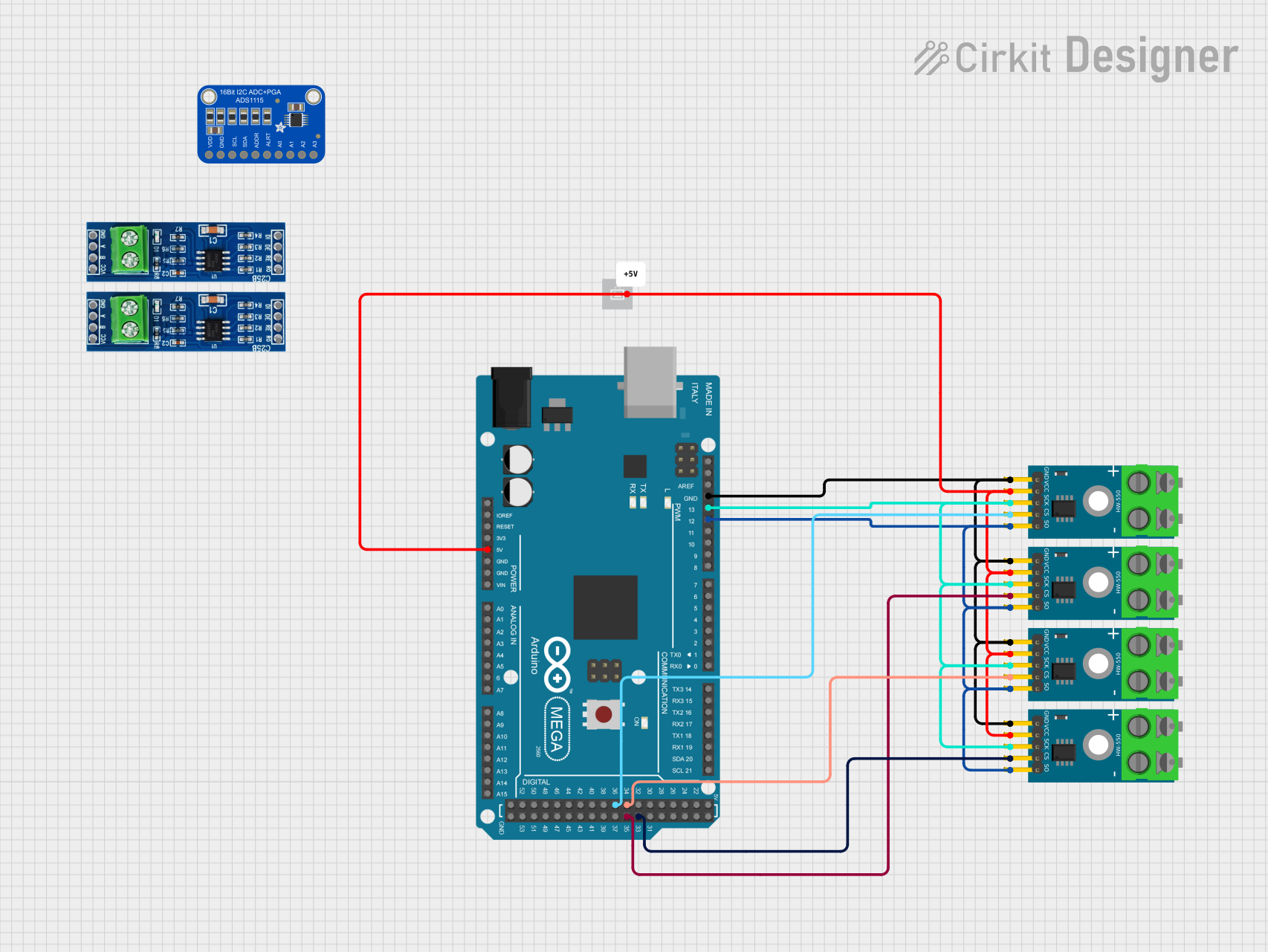
This circuit integrates an Arduino Mega 2560 with multiple MAX6675 thermocouple modules to measure temperatures and a +5V power supply to provide the necessary voltage. The MAX6675 modules are interfaced with the Arduino Mega 2560 for temperature data acquisition. The Arduino Mega 2560 serves as the central processing unit, handling the data from the MAX6675 modules and potentially performing further processing or communication tasks.
Component List
Arduino Mega 2560
- Microcontroller board based on the ATmega2560
- Offers 54 digital input/output pins, 16 analog inputs, 4 UARTs, a 16 MHz crystal oscillator, a USB connection, a power jack, an ICSP header, and a reset button.
MAX485
- Transceiver module for RS-485 communication.
MAX6675 Module
- Thermocouple-to-digital converter that requires a supply voltage of 3.0 to 5.5V and provides a digital output proportional to the temperature.
Adafruit ADS1115 16-Bit I2C ADC
- Precision analog-to-digital converter (ADC) with 16-bit resolution offered in an ultra-small, leadless QFN-10 package or an MSOP-10 package.
+5V Power Supply
- Provides a stable +5V supply voltage.
Comment
- A placeholder for additional notes or comments about the circuit.
Wiring Details
Arduino Mega 2560
5Vconnected to the VCC of all MAX6675 Modules and +5V power supply.GNDconnected to the GND of all MAX6675 Modules.D12 PWMconnected to the SO (Serial Output) pin of all MAX6675 Modules.D13 PWMconnected to the SCK (Serial Clock) pin of all MAX6675 Modules.D36connected to the CS (Chip Select) pin of one MAX6675 Module.D34connected to the CS (Chip Select) pin of another MAX6675 Module.D35connected to the CS (Chip Select) pin of another MAX6675 Module.D33connected to the CS (Chip Select) pin of another MAX6675 Module.
MAX6675 Modules
VCCconnected to the 5V output from the Arduino Mega 2560 and +5V power supply.GNDconnected to the GND on the Arduino Mega 2560.SCKconnected to the D13 PWM on the Arduino Mega 2560.CSconnected to individual digital pins (D36, D34, D35, D33) on the Arduino Mega 2560 for each module.SOconnected to the D12 PWM on the Arduino Mega 2560.
+5V Power Supply
+5Vconnected to the VCC of all MAX6675 Modules and the 5V pin on the Arduino Mega 2560.
Documented Code
Arduino Mega 2560 - sketch.ino
void setup() {
  // put your setup code here, to run once:

}

void loop() {
  // put your main code here, to run repeatedly:

}
Arduino Mega 2560 - documentation.txt
(No additional documentation provided)
This concludes the documentation for the provided circuit. The code provided is a template and does not include specific functionality. It should be expanded to initialize the communication with the MAX6675 modules, read temperature data, and handle any required processing or output.