
Circuit Documentation
Summary of the Circuit
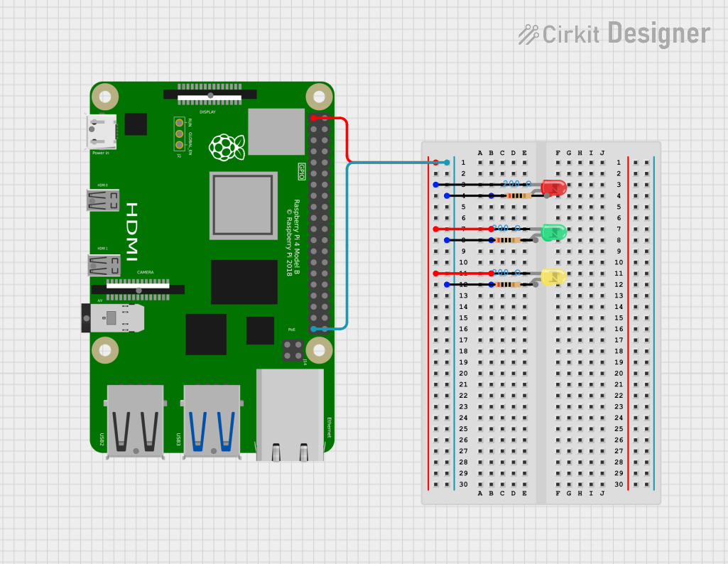
This circuit appears to be a simple LED array controlled by a Raspberry Pi 4B. There are three LEDs of different colors (red, green, and yellow), each with a corresponding resistor. The anodes of the LEDs are connected to the 3V3 power supply from the Raspberry Pi, while the cathodes are connected to ground (GND) through their respective resistors. This configuration suggests that the LEDs are intended to be driven by the Raspberry Pi's GPIO pins, although the specific control mechanism is not provided in the code input.
Component List
LED: Two Pin (red)
- Description: A red LED with two pins: anode and cathode.
- Purpose: To emit red light when powered.
LED: Two Pin (green)
- Description: A green LED with two pins: anode and cathode.
- Purpose: To emit green light when powered.
LED: Two Pin (yellow)
- Description: A yellow LED with two pins: anode and cathode.
- Purpose: To emit yellow light when powered.
Resistor (200 Ohms)
- Description: A resistor with a resistance of 200 Ohms.
- Purpose: To limit the current flowing through the LEDs, protecting them from damage.
Raspberry Pi 4B
- Description: A microcontroller board with multiple GPIO pins and power supply pins.
- Purpose: To control the LEDs and potentially perform other computational tasks.
Wiring Details
LED: Two Pin (red)
- Anode: Connected to the 3V3 power supply from the Raspberry Pi.
- Cathode: Connected to a 200 Ohm resistor, which is then connected to GND on the Raspberry Pi.
LED: Two Pin (green)
- Anode: Connected to the 3V3 power supply from the Raspberry Pi.
- Cathode: Connected to a 200 Ohm resistor, which is then connected to GND on the Raspberry Pi.
LED: Two Pin (yellow)
- Anode: Connected to the 3V3 power supply from the Raspberry Pi.
- Cathode: Connected to a 200 Ohm resistor, which is then connected to GND on the Raspberry Pi.
Resistor (200 Ohms)
- Pin1: Connected to the cathode of the corresponding LED.
- Pin2: Connected to the GND pin on the Raspberry Pi.
Raspberry Pi 4B
- 3V3: Provides power to the anodes of all three LEDs.
- GND: Connected to the second pin of all three resistors, completing the circuit for each LED.
Documented Code
No code was provided for the microcontroller in the circuit. To control the LEDs, code would need to be written and deployed to the Raspberry Pi 4B. This code would typically initialize the GPIO pins as outputs and then toggle them to turn the LEDs on and off. Since no code is available, this section cannot be completed at this time.