ESP32-Controlled Traffic Light and DC Motors with MT3608 Boost Converters

Circuit Documentation
Summary
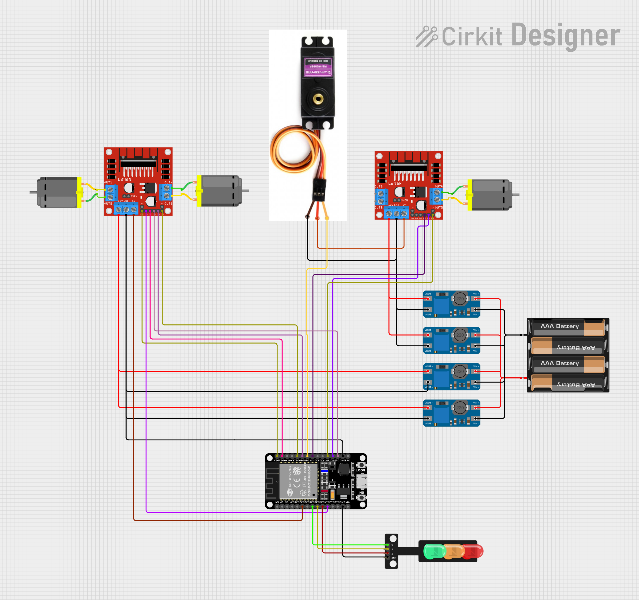
This circuit is designed to control a traffic light and multiple DC motors using an ESP32 microcontroller and L298N motor drivers. The ESP32 is responsible for the logic control, sending signals to the traffic light and motor drivers. The MT3608 modules are used to step up the voltage from a 4 x AAA battery mount to power the L298N motor drivers and the servo motor. The MG996R servo motor is controlled directly by the ESP32. The DC motors are driven by the L298N motor drivers, which receive control signals from the ESP32.
Component List
Microcontroller
- ESP32 (30 pin): A microcontroller with WiFi and Bluetooth capabilities, featuring a wide range of GPIO pins for interfacing with various components.
Motor Drivers
- L298N DC motor driver: A dual H-bridge motor driver capable of driving two DC motors or one stepper motor.
Motors
- MG996R: A high-torque servo motor used for precise angular movement.
- DC Motor: A standard DC motor for rotational motion.
Power Modules
- MT3608: A DC-DC step-up converter module used to increase the voltage level from the battery to the required level for the motor drivers and servo motor.
Power Supply
- 4 x AAA Battery Mount: A battery holder for four AAA batteries, providing the power source for the circuit.
Output Devices
- Traffic Light: A simple traffic light module with red, yellow, and green LEDs.
Wiring Details
ESP32 (30 pin)
D32connected to L298N DC motor driver (5V input for logic)D25connected to Traffic Light (Green LED control)D26connected to Traffic Light (Yellow LED control)D27connected to Traffic Light (Red LED control)D14connected to L298N DC motor driver (IN1 control)GNDconnected to Traffic Light (GND), L298N DC motor driver (GND), and MT3608 modules (GND)D23connected to L298N DC motor driver (ENA control)D22connected to L298N DC motor driver (IN2 control)D21connected to L298N DC motor driver (ENB control)D19connected to L298N DC motor driver (IN4 control)D18connected to MG996R (Signal Line control)D5connected to L298N DC motor driver (IN3 control)D4connected to L298N DC motor driver (ENB control)D2connected to L298N DC motor driver (IN4 control)D15connected to L298N DC motor driver (IN3 control)
L298N DC motor driver
5Vconnected to ESP32 (D32) and MG996R (Vcc)GNDconnected to ESP32 (GND), MT3608 modules (GND), and MG996R (GND)12Vconnected to MT3608 modules (VOUT+)ENA,IN1,IN2,ENB,IN3,IN4connected to ESP32 (D23, D14, D22, D21, D15, D19 respectively)OUT1,OUT2,OUT3,OUT4connected to DC Motors
MT3608
VOUT+connected to L298N DC motor driver (12V input)VOUT-connected to ESP32 (GND) and L298N DC motor driver (GND)VIN+connected to 4 x AAA Battery Mount (+)VIN-connected to 4 x AAA Battery Mount (-)
MG996R
Signal Lineconnected to ESP32 (D18)Vccconnected to L298N DC motor driver (5V)GNDconnected to ESP32 (GND) and L298N DC motor driver (GND)
4 x AAA Battery Mount
+connected to MT3608 modules (VIN+)-connected to MT3608 modules (VIN-)
DC Motor
pin 1andpin 2connected to L298N DC motor driver (OUT1, OUT2, OUT3, OUT4)
Traffic Light
Greenconnected to ESP32 (D25)Yellowconnected to ESP32 (D26)Redconnected to ESP32 (D27)GNDconnected to ESP32 (GND)
Documented Code
No code was provided for the microcontroller. The documentation of the code would typically include the setup and loop functions for the ESP32, detailing how the GPIO pins are configured and how they control the traffic light and motors. It would also include any necessary libraries, functions, and routines to handle WiFi or Bluetooth functionalities if used in the circuit.