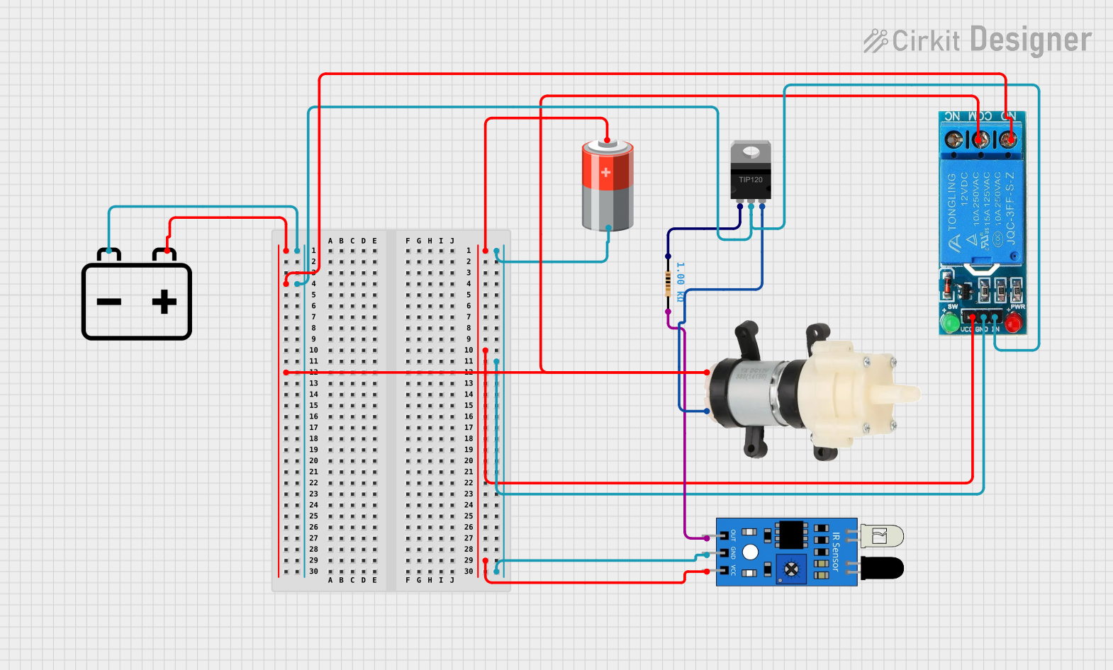
IR Sensor-Activated Water Pump with Relay Control

Circuit Documentation
Summary of the Circuit
This circuit appears to be designed to control a Mini Diaphragm Water Pump using a 12V SINGLE CHANNEL RELAY which is triggered by an IR sensor. The relay allows the 12V battery to power the pump when the IR sensor detects the presence of an object. A TIP120 Hi-Current Darlington Transistor is used to interface the low-power output from the IR sensor with the higher power requirement of the relay's control input. A 5V battery is used to power the IR sensor and the relay's control circuitry. A resistor is included in the circuit, likely for current limiting purposes to protect the transistor's base.
Component List
12v Battery
- Description: A 12-volt battery providing the main power source for the water pump and the relay's switching mechanism.
5v Battery
- Description: A 5-volt battery used to power the IR sensor and the relay's control circuitry.
IR Sensor
- Description: An infrared sensor used to detect the presence of an object and trigger the relay.
Mini Diaphragm Water Pump
- Description: A pump that is powered by the 12V battery and controlled by the relay.
TIP120 Hi-Current Darlington Transistor
- Description: A transistor that acts as a switch to control the relay with the signal from the IR sensor.
12V SINGLE CHANNEL RELAY
- Description: A relay that switches the water pump on and off based on the signal from the IR sensor.
Resistor
- Description: A 1000 Ohm resistor used for current limiting to protect the transistor.
Wiring Details
12v Battery
- Positive (+) connected to the relay's Normally Open (NO) contact and the water pump's Positive (+) terminal.
- Negative (-) connected to the Collector of the TIP120 transistor and the relay's Input (IN).
5v Battery
- Positive (+) connected to the relay's Voltage Supply (VCC) and the IR sensor's VCC pin.
- Negative (-) connected to the relay's Ground (GND) and the IR sensor's GND pin.
IR Sensor
- Output (out) connected to one end of the resistor (pin2).
- Ground (gnd) connected to the 5v Battery's Negative (-) and the relay's GND.
- VCC connected to the 5v Battery's Positive (+).
Mini Diaphragm Water Pump
- Positive (+) connected to the relay's Common (COM) contact.
- Negative (-) connected to the Emitter of the TIP120 transistor.
TIP120 Hi-Current Darlington Transistor
- Base (BASE) connected to one end of the resistor (pin1).
- Collector (COLLECTOR) connected to the 12v Battery's Negative (-).
- Emitter (EMITTER) connected to the water pump's Negative (-) terminal.
12V SINGLE CHANNEL RELAY
- Normally Closed (NC) not connected.
- Common (COM) connected to the water pump's Positive (+) terminal.
- Normally Open (NO) connected to the 12v Battery's Positive (+).
- Input (IN) connected to the 12v Battery's Negative (-).
- Ground (GND) connected to the 5v Battery's Negative (-).
- Voltage Supply (VCC) connected to the 5v Battery's Positive (+).
Resistor
- One end (pin1) connected to the Base of the TIP120 transistor.
- The other end (pin2) connected to the IR sensor's output.
Documented Code
There is no code provided for any microcontrollers in this circuit. If the circuit is intended to be controlled by a microcontroller, the code would be necessary to define the behavior of the microcontroller in response to the IR sensor's output and to control the relay accordingly. Without the code, the circuit is assumed to be a simple hardware-only control system where the IR sensor directly triggers the relay through the transistor.