
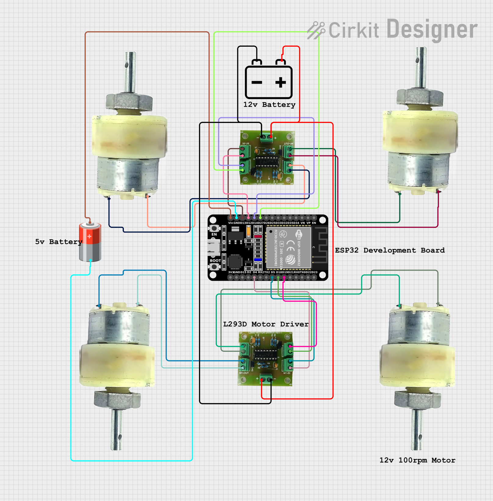
Circuit Documentation
Summary
This circuit is designed to control four 12V geared motors using two L293D motor driver ICs, which are interfaced with an ESP32 microcontroller. The ESP32 is responsible for generating control signals to drive the motors in forward, backward, left, and right directions. The motors are powered by a 12V battery, while the ESP32 is powered by a separate 5V battery to ensure stable operation. The circuit includes provisions for motor control through GPIO pins and includes a delay-based sequence in the embedded code to demonstrate the motor control functionality.
Component List
ESP32 (30 pin)
- Description: A microcontroller with WiFi and Bluetooth capabilities, featuring a wide range of GPIO pins for interfacing with various peripherals.
- Pins: EN, VP, VN, D34, D35, D32, D33, D25, D26, D27, D14, D12, D13, GND, Vin, D23, D22, TX0, RX0, D21, D19, D18, D5, TX2, RX2, D4, D2, D15, 3V3
L293D Motor Driver IC
- Description: A dual H-bridge motor driver IC capable of driving two motors simultaneously in both directions.
- Pins: Battery +, Battery -, M1-OUT-A, M1-OUT-B, M2-OUT-B, M2-OUT-A, M1-IN-A, M1-IN-B, M2-IN-A, M2-IN-B
12V Geared Motor
- Description: A motor designed for high torque applications, typically used in robotics and automation projects.
- Pins: Terminal 1, Terminal 2
5V Battery
- Description: A power source used to supply the ESP32 microcontroller.
- Pins: +, -
12V Battery
- Description: A power source used to supply the motors through the L293D motor driver ICs.
- Pins: +, -
Wiring Details
ESP32 (30 pin)
- D27 connected to L293D M2-IN-B
- D14 connected to L293D M2-IN-A
- D12 connected to L293D M1-IN-B
- D13 connected to L293D M1-IN-A
- GND connected to 5V Battery -
- Vin connected to 5V Battery +
L293D Motor Driver IC (First Instance)
- M2-IN-B connected to ESP32 D27
- M2-IN-A connected to ESP32 D14
- M1-IN-B connected to ESP32 D12
- M1-IN-A connected to ESP32 D13
- Battery + connected to 12V Battery +
- Battery - connected to 12V Battery -
- M1-OUT-A connected to 12V Geared Motor Terminal 1
- M1-OUT-B connected to 12V Geared Motor Terminal 2
- M2-OUT-B connected to 12V Geared Motor Terminal 1
- M2-OUT-A connected to 12V Geared Motor Terminal 2
L293D Motor Driver IC (Second Instance)
- M2-IN-B connected to ESP32 D19
- M2-IN-A connected to ESP32 D18
- M1-IN-B connected to ESP32 D5
- M1-IN-A connected to ESP32 D4
- Battery + connected to 12V Battery +
- Battery - connected to 12V Battery -
- M1-OUT-A connected to 12V Geared Motor Terminal 1
- M1-OUT-B connected to 12V Geared Motor Terminal 2
- M2-OUT-B connected to 12V Geared Motor Terminal 2
- M2-OUT-A connected to 12V Geared Motor Terminal 1
12V Geared Motors
- Terminal 1 and Terminal 2 connected to respective outputs of L293D motor driver ICs.
5V Battery
-
- connected to ESP32 Vin
-
- connected to ESP32 GND
12V Battery
-
- connected to L293D Battery +
-
- connected to L293D Battery -
Documented Code
// Define motor control pins
int A=4, B=5, C=18, D=19;
int E=13, F=12, G=14, H=27;
int t=1000; // Delay time in milliseconds

// Function prototypes for motor control
void f_w();
void b_w();
void r_w();
void l_w();

void setup()
{
  // Initialize motor control pins as outputs
  pinMode(A,OUTPUT);
  pinMode(B,OUTPUT);
  pinMode(C,OUTPUT);
  pinMode(D,OUTPUT);
  pinMode(E,OUTPUT);
  pinMode(F,OUTPUT);
  pinMode(G,OUTPUT);
  pinMode(H,OUTPUT);
}

void loop()
{
  // Sequence of motor movements
  f_w(); // Forward
  delay(t);
  b_w(); // Backward
  delay(t);
  r_w(); // Right
  delay(t);
  l_w(); // Left
  delay(t);
}

// Function to move forward
void f_w()
{
  digitalWrite(A,1);
  digitalWrite(B,0);
  digitalWrite(C,1);
  digitalWrite(D,0);
  digitalWrite(E,1);
  digitalWrite(F,0);
  digitalWrite(G,1);
  digitalWrite(H,0);
}

// Function to move backward
void b_w()
{
  digitalWrite(A,0);
  digitalWrite(B,1);
  digitalWrite(C,0);
  digitalWrite(D,1);
  digitalWrite(E,0);
  digitalWrite(F,1);
  digitalWrite(G,0);
  digitalWrite(H,1);
}

// Function to turn right
void r_w()
{
  digitalWrite(A,1);
  digitalWrite(B,0);
  digitalWrite(C,1);
  digitalWrite(D,0);
  digitalWrite(E,0);
  digitalWrite(F,0);
  digitalWrite(G,0);
  digitalWrite(H,0);
}

// Function to turn left
void l_w()
{
  digitalWrite(A,0);
  digitalWrite(B,1);
  digitalWrite(C,0);
  digitalWrite(D,1);
  digitalWrite(E,0);
  digitalWrite(F,0);
  digitalWrite(G,0);
  digitalWrite(H,0);
}
The code provided is for the ESP32 microcontroller and is written in Arduino C/C++. It defines a set of functions to control the motors connected through the L293D motor driver ICs. The setup() function initializes the GPIO pins as outputs, and the loop() function calls the motor control functions in a sequence to demonstrate the motor's forward, backward, right, and left movements. Each motor control function sets the appropriate GPIO pins high or low to control the direction of the motors.