
Circuit Documentation
Summary
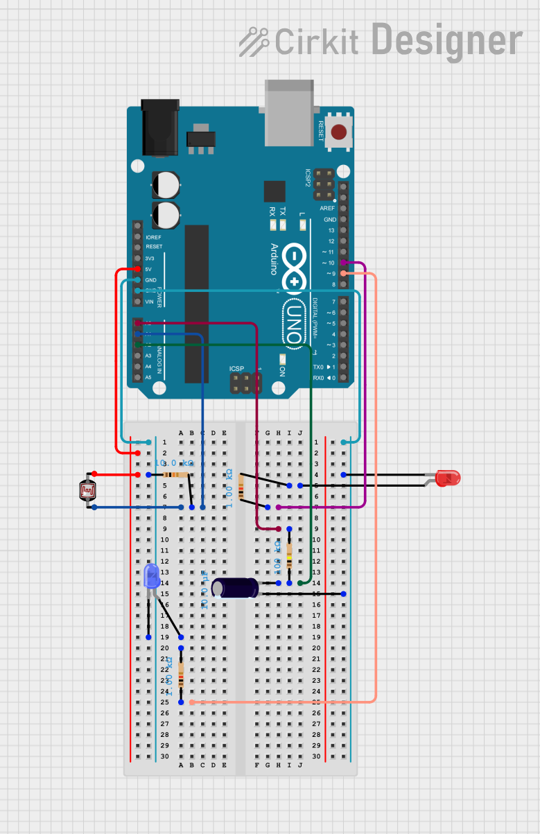
This document provides a detailed overview of a circuit that includes various electronic components such as LEDs, resistors, an Arduino UNO microcontroller, an electrolytic capacitor, and a photocell (LDR). The circuit is designed to interface with the Arduino UNO, which controls and monitors the components. The LEDs are used as indicators, the resistors set current limits and voltage dividers, the capacitor provides stability, and the photocell senses ambient light levels.
Component List
LED: Two Pin (red)
- Description: A red LED used as an indicator.
- Pins: cathode, anode
LED: Two Pin (blue)
- Description: A blue LED used as an indicator.
- Pins: cathode, anode
Resistor (1k Ohms)
- Description: A resistor with a resistance of 1k Ohms.
- Pins: pin1, pin2
Resistor (10k Ohms)
- Description: A resistor with a resistance of 10k Ohms.
- Pins: pin1, pin2
Resistor (100k Ohms)
- Description: A resistor with a resistance of 100k Ohms.
- Pins: pin1, pin2
Arduino UNO
- Description: A microcontroller board based on the ATmega328P.
- Pins: UNUSED, IOREF, Reset, 3.3V, 5V, GND, Vin, A0 to A5, SCL, SDA, AREF, D0 to D13
Electrolytic Capacitor (10uF)
- Description: An electrolytic capacitor with a capacitance of 10uF.
- Pins: -, +
Photocell (LDR)
- Description: A light-dependent resistor used for sensing light levels.
- Pins: pin 0, pin 1
Wiring Details
LED: Two Pin (red)
- Cathode: Connected to GND on the Arduino UNO.
- Anode: Connected to one end of a 1k Ohm resistor, whose other end is connected to pin D10 on the Arduino UNO.
LED: Two Pin (blue)
- Cathode: Connected to GND on the Arduino UNO.
- Anode: Connected to one end of a 10k Ohm resistor, whose other end is connected to pin D9 on the Arduino UNO.
Resistor (1k Ohms)
- Pin1: Connected to the anode of the red LED.
- Pin2: Connected to pin D10 on the Arduino UNO.
Resistor (10k Ohms)
- Pin1: Connected to the anode of the blue LED.
- Pin2: Connected to pin D9 on the Arduino UNO.
Resistor (100k Ohms)
- Pin1: Connected to the positive pin of the electrolytic capacitor and pin A2 on the Arduino UNO.
- Pin2: Connected to GND on the Arduino UNO.
Arduino UNO
- 5V: Connected to pin 1 of the photocell (LDR).
- GND: Connected to the cathodes of both the red and blue LEDs, and one end of the 100k Ohm resistor.
- A0: Connected to one end of a 100k Ohm resistor.
- A1: Connected to the junction between the 10k Ohm resistor and pin 0 of the photocell (LDR).
- A2: Connected to the positive pin of the electrolytic capacitor and one end of a 100k Ohm resistor.
- D9: Connected to one end of a 10k Ohm resistor.
- D10: Connected to one end of a 1k Ohm resistor.
Electrolytic Capacitor (10uF)
- -: Connected to the cathode of the red LED.
- +: Connected to the positive pin of the electrolytic capacitor and one end of a 100k Ohm resistor.
Photocell (LDR)
- Pin 0: Connected to the junction between the 10k Ohm resistor and pin A1 on the Arduino UNO.
- Pin 1: Connected to 5V on the Arduino UNO.
Documented Code
Arduino UNO Code (sketch.ino)
void setup() {
  // put your setup code here, to run once:

}

void loop() {
  // put your main code here, to run repeatedly:

}
Additional Notes (documentation.txt)
No additional code documentation was provided.