
Circuit Documentation
Summary
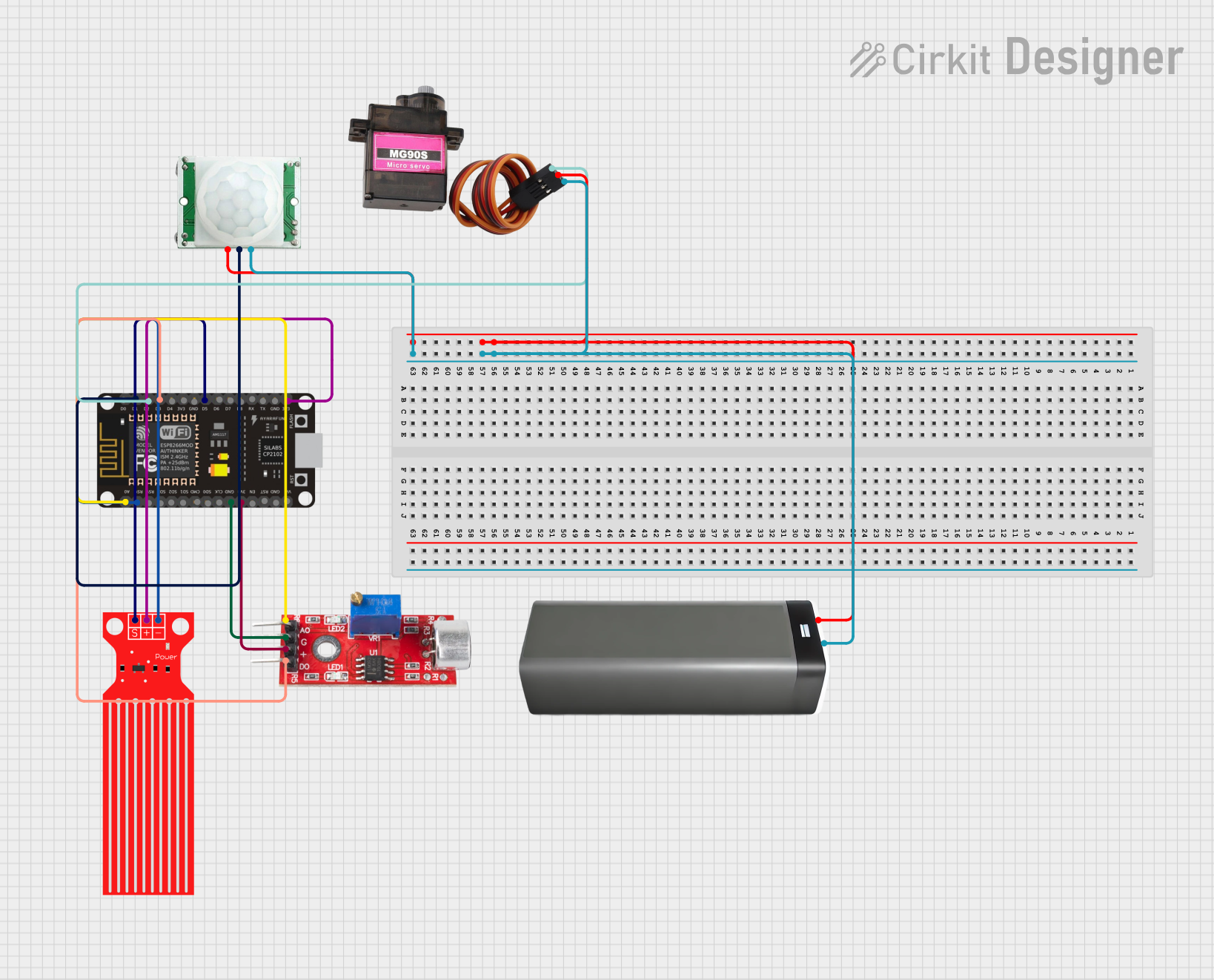
The circuit in question is designed to interface an ESP8266 NodeMCU microcontroller with a variety of sensors and a servo motor. The sensors include a water level sensor, a sound sensor, and a PIR/motion sensor. A battery pack provides the power supply for the servo motor and the PIR/motion sensor. The ESP8266 NodeMCU is responsible for processing the signals from these sensors and controlling the servo motor based on the sensor inputs. The water level sensor and the sound sensor are powered by the 3.3V output from the ESP8266 NodeMCU.
Component List
ESP8266 NodeMCU
- Description: A WiFi-capable microcontroller module based on the ESP8266 chip.
- Pins: D0, D1, D2, D3, D4, 3V3, GND, D5, D6, D7, D8, RX, TX, A0, RSV, SD3, SD2, SD1, CMD, SD0, CLK, EN, RST, VIN
Water Level Sensor
- Description: A sensor that detects the level of water in a container.
- Pins: SIG, VCC, GND
Sound Sensor
- Description: A sensor that detects sound intensity and provides both analog and digital outputs.
- Pins: Analog, GND, VCC, Digital
MG90S (Servo Motor)
- Description: A micro servo motor that can be precisely controlled.
- Pins: SIG, VCC, GND
PIR/Motion Sensor
- Description: A sensor that detects motion within its field of view.
- Pins: GND, OUTPUT, VCC
Battery Pack
- Description: A power source for the circuit.
- Pins: +, -
Wiring Details
ESP8266 NodeMCU
- D1 connected to PIR/Motion Sensor OUTPUT
- D2 connected to MG90S SIG
- D3 connected to Sound Sensor Digital
- D5 connected to Water Level Sensor SIG
- A0 connected to Sound Sensor Analog
- 3V3 connected to Water Level Sensor VCC and Sound Sensor VCC
- GND connected to Water Level Sensor GND and Sound Sensor GND
- RSV connected to Water Level Sensor GND
Water Level Sensor
- SIG connected to ESP8266 NodeMCU D5
- VCC connected to ESP8266 NodeMCU 3V3
- GND connected to ESP8266 NodeMCU RSV
Sound Sensor
- Analog connected to ESP8266 NodeMCU A0
- Digital connected to ESP8266 NodeMCU D3
- VCC connected to ESP8266 NodeMCU 3V3
- GND connected to ESP8266 NodeMCU GND
MG90S (Servo Motor)
- SIG connected to ESP8266 NodeMCU D2
- VCC connected to Battery Pack +
- GND connected to Battery Pack -
PIR/Motion Sensor
- OUTPUT connected to ESP8266 NodeMCU D1
- VCC connected to Battery Pack +
- GND connected to Battery Pack -
Battery Pack
-
- connected to MG90S VCC and PIR/Motion Sensor VCC
-
- connected to MG90S GND and PIR/Motion Sensor GND
Documented Code
No code has been provided for the microcontroller. The documentation of the code would typically include a description of the functionality, setup, and loop functions, along with any functions used to read sensor data or control the servo motor. Since no code is available, this section cannot be completed.