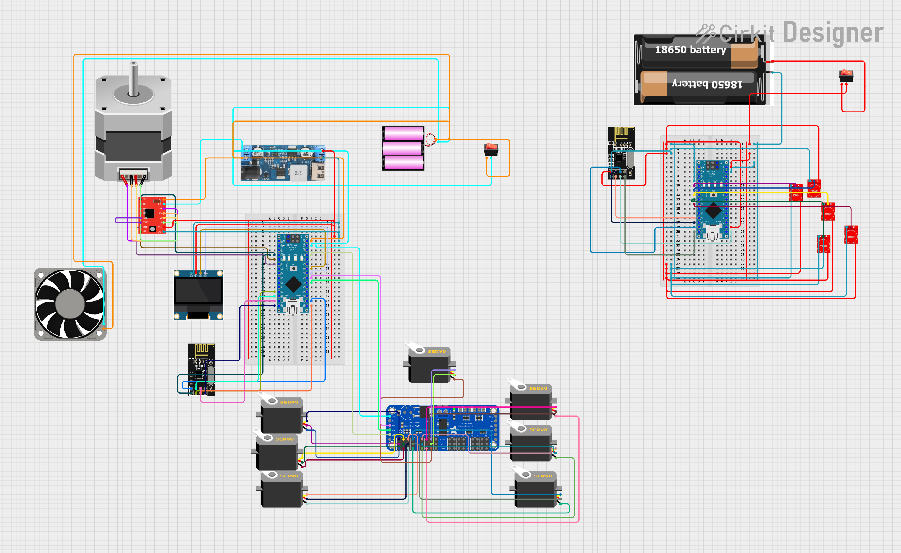
Arduino Nano Controlled Robotics System with Wireless Communication and Touch Sensing

Circuit Documentation
Summary
This circuit is designed to control a variety of components including servos, a stepper motor, touch sensors, a display, and wireless communication modules. It is powered by a 12V battery and includes voltage regulation to provide 5V where needed. The circuit is controlled by two Arduino Nano microcontrollers, which interface with an Adafruit 16-Channel PWM Servo Driver, touch sensors, an OLED display, NRF24L01 wireless communication modules, and an A4988 stepper motor driver. The system also includes a 12V fan and power management through rocker switches.
Component List
Microcontrollers
- Arduino Nano: A compact microcontroller board based on the ATmega328P, featuring digital and analog I/O pins.
Power Components
- Battery 12V: Provides the main power source for the circuit.
- 2x 18650 Batteries: Secondary power source for part of the circuit.
- 12V to 5V Step Down Power Converter: Converts the 12V supply to 5V for components requiring lower voltage.
- Rocker Switches: Used to control the power flow in the circuit.
Actuators
- Servos: Actuators that can be positioned to specific angles using PWM signals.
- Stepper Motor (Bipolar): A motor that moves in discrete steps, controlled by the A4988 driver.
- 40 Fan 12V: A cooling fan operating at 12V.
Sensors and Input Devices
- Touch Sensor TTP233: Capacitive touch sensors used as input devices.
Communication Modules
- NRF24L01: Wireless communication modules for remote data transmission.
Display
- 0.96" OLED: A small display for visual output.
Motor Drivers
- A4988 Stepper Motor Driver (Red): A driver module for controlling bipolar stepper motors.
PWM Driver
- Adafruit 16-Channel 12-bit PWM Servo Driver - I2C: A driver board for controlling up to 16 servos via I2C communication.
Wiring Details
Arduino Nano
- VIN: Connected to the rocker switch and the 12V battery for power input.
- GND: Common ground with various components.
- 5V: Powers the Adafruit PWM Servo Driver.
- Digital Pins (D2-D13): Control signals for the A4988 driver, NRF24L01 module, and touch sensors.
- Analog Pins (A2-A5): I2C communication with the OLED display and Adafruit PWM Servo Driver.
Adafruit 16-Channel PWM Servo Driver - I2C
- 5.0V: Power input from the Arduino Nano 5V pin.
- VCC: Logic level power input from the Arduino Nano 5V pin.
- SDA/SCL: I2C communication with the Arduino Nano.
- GND: Connected to the common ground.
- PWM0-PWM6: PWM outputs to control individual servos.
Touch Sensor TTP233
- VCC: Powered by the 3.3V output from the Arduino Nano.
- GND: Connected to the common ground.
- I/O: Signal connected to digital pins on the Arduino Nano.
Servo
- VCC: Powered by the 5.0V output from the Adafruit PWM Servo Driver.
- GND: Connected to the common ground.
- Pulse: PWM signal input from the Adafruit PWM Servo Driver.
Stepper Motor (Bipolar)
- A, B, C, D: Connected to the A4988 Stepper Motor Driver outputs.
0.96" OLED
- VDD: Powered by the 5V output from the step-down converter.
- GND: Connected to the common ground.
- SCK/SDA: I2C communication with the Arduino Nano.
NRF24L01
- VCC (3V): Powered by the 3.3V output from the Arduino Nano.
- GND: Connected to the common ground.
- CE, CSN, MOSI, MISO, SCK: SPI communication with the Arduino Nano.
A4988 Stepper Motor Driver (Red)
- VMOT: Motor power input from the 12V battery.
- GND: Connected to the common ground.
- VDD: Logic level power input from the 5V output of the step-down converter.
- 1A, 1B, 2A, 2B: Outputs to the stepper motor.
- DIR, STEP: Control inputs from the Arduino Nano.
- ENABLE, RESET, SLEEP: Configuration pins, with RESET and SLEEP tied together.
Documented Code
Arduino Nano (Primary Controller)
void setup() {
  // put your setup code here, to run once:

}

void loop() {
  // put your main code here, to run repeatedly:

}
Arduino Nano (Secondary Controller)
void setup() {
  // put your setup code here, to run once:

}

void loop() {
  // put your main code here, to run repeatedly:

}
Note: The provided code snippets are templates and do not contain specific logic for controlling the circuit components. The actual implementation should include initialization of I/O pins, communication setup, and control algorithms based on the application requirements.