
Arduino UNO-Based Temperature-Controlled Fan and Heater System with DHT11 Sensor and LCD Display
View and Edit Project In Cirkit Designer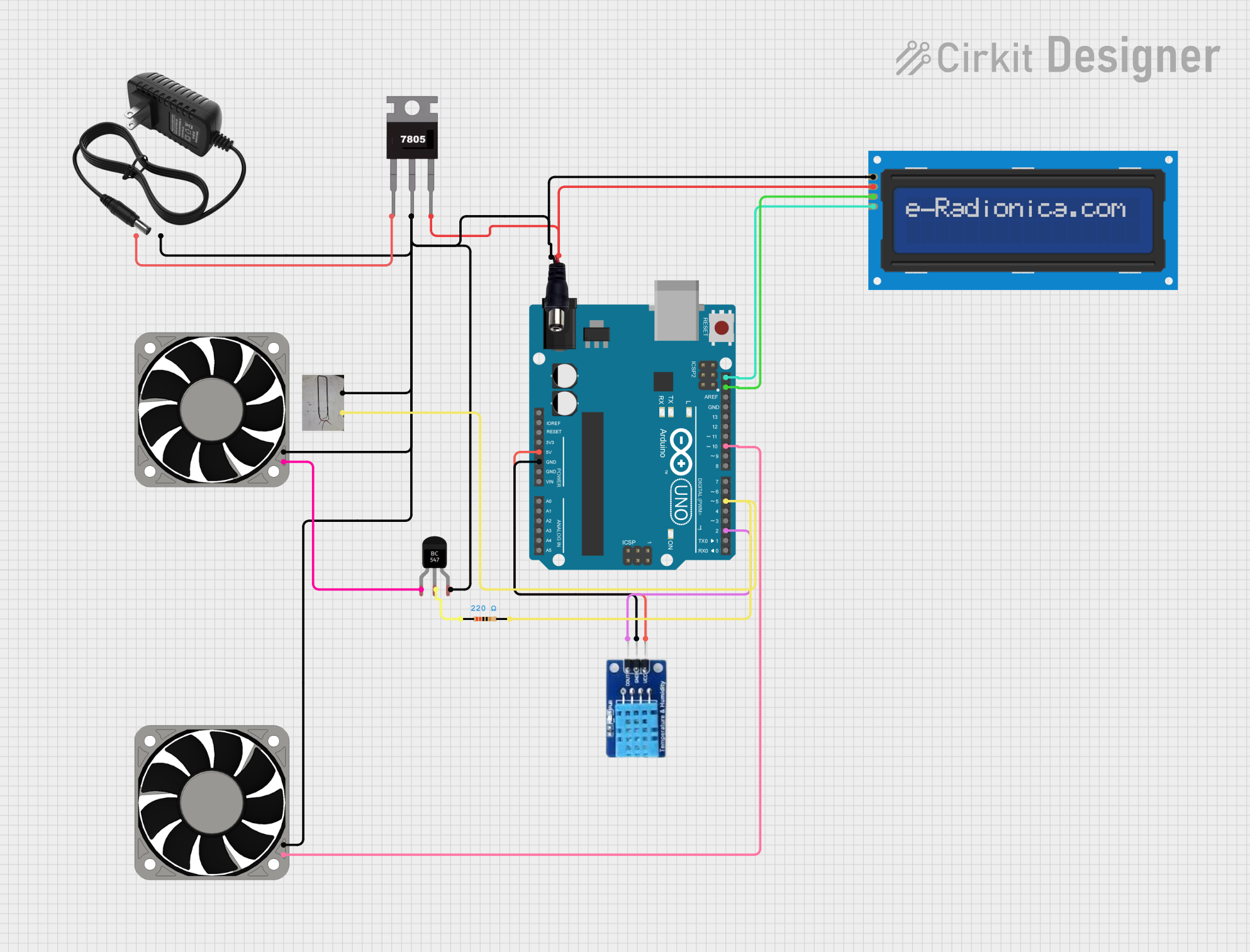
Circuit Documentation
Summary
This circuit is designed to control a 12V fan and a 400W heater based on temperature readings from a DHT11 sensor. The temperature data is displayed on a 16x2 I2C LCD screen. The circuit is powered by a 12V power supply, which is regulated to 5V using a 7805 voltage regulator to power the Arduino UNO and other 5V components.
Component List
Arduino UNO
- Description: Microcontroller board based on the ATmega328P.
- Pins: UNUSED, IOREF, Reset, 3.3V, 5V, GND, Vin, A0, A1, A2, A3, A4, A5, SCL, SDA, AREF, D13, D12, D11, D10, D9, D8, D7, D6, D5, D4, D3, D2, D1, D0
7805
- Description: Voltage regulator that converts 12V to 5V.
- Pins: Vin, Gnd, Vout
Power Jack
- Description: Connector for the 12V power supply.
- Pins: POSITIF, NEGATIF
Resistor (220 Ohms)
- Description: Resistor used for current limiting.
- Pins: pin1, pin2
- Properties: Resistance: 220 Ohms
DHT11
- Description: Temperature and humidity sensor.
- Pins: DATA, GND, VCC
LCD Screen 16x2 I2C
- Description: 16x2 character LCD display with I2C interface.
- Pins: SCL, SDA, VCC, GND
12V Power Supply
- Description: Power supply providing 12V DC.
- Pins: +, -
40 Fan 12V
- Description: 12V DC fan.
- Pins: +12V, -12V
400W Resistor (Heater)
- Description: High-power resistor used as a heater.
- Pins: GND, VCC
BC547 Transistor
- Description: NPN transistor used for switching.
- Pins: Collector, Base, Emitter
Wiring Details
Arduino UNO
- 5V to DHT11 VCC
- GND to DHT11 GND
- SCL to LCD Screen 16x2 I2C SCL
- SDA to LCD Screen 16x2 I2C SDA
- D10 to 40 Fan 12V +12V
- D5 to Resistor pin2 (which is connected to 400W Resistor VCC)
- D2 to DHT11 DATA
7805
- Vin to 12V Power Supply +
- Gnd to Power Jack NEGATIF, 400W Resistor GND, 12V Power Supply -, LCD Screen 16x2 I2C GND, BC547 Transistor Emitter, 40 Fan 12V -12V
- Vout to Power Jack POSITIF, LCD Screen 16x2 I2C VCC
Power Jack
- POSITIF to 7805 Vout
- NEGATIF to 7805 Gnd
Resistor (220 Ohms)
- pin1 to BC547 Transistor Base
- pin2 to Arduino UNO D5
DHT11
- VCC to Arduino UNO 5V
- GND to Arduino UNO GND
- DATA to Arduino UNO D2
LCD Screen 16x2 I2C
- SCL to Arduino UNO SCL
- SDA to Arduino UNO SDA
- VCC to 7805 Vout
- GND to 7805 Gnd
12V Power Supply
- + to 7805 Vin
- - to 7805 Gnd
40 Fan 12V
- +12V to Arduino UNO D10
- -12V to 7805 Gnd
400W Resistor (Heater)
- GND to Power Jack NEGATIF
- VCC to Resistor pin2
BC547 Transistor
- Collector to 40 Fan 12V +12V
- Base to Resistor pin1
- Emitter to 7805 Gnd
Code Documentation
#include <DHT.h>

#define DHTPIN 2          // Pin where the DHT sensor is connected
#define DHTTYPE DHT11     // DHT 11
#define FAN_PIN 9         // Pin for the fan (PWM)

DHT dht(DHTPIN, DHTTYPE);

void setup() {
  Serial.begin(9600);
  dht.begin();
  pinMode(FAN_PIN, OUTPUT);
}

void loop() {
  delay(2000);

  float h = dht.readHumidity();
  float t = dht.readTemperature(); // Read temperature in Celsius

  if (isnan(h) || isnan(t)) {
    Serial.println("Error reading DHT sensor!");
    return;
  }

  Serial.print("Temperature: ");
  Serial.print(t);
  Serial.println(" *C");

  // Fan control
  if (t < 15) {
    // Turn on heater
    analogWrite(FAN_PIN, 255); // 100% speed
  } else if (t > 25) {
    // Turn on fan
    analogWrite(FAN_PIN, 255); // 100% speed
  } else if (t >= 19 && t <= 25) {
    // Turn off fan
    analogWrite(FAN_PIN, 0); // 0% speed
  }
}
This code reads temperature and humidity data from the DHT11 sensor and controls the fan based on the temperature readings. The fan is turned on at full speed if the temperature is below 15°C (heater mode) or above 25°C (cooling mode). The fan is turned off if the temperature is between 19°C and 25°C.