
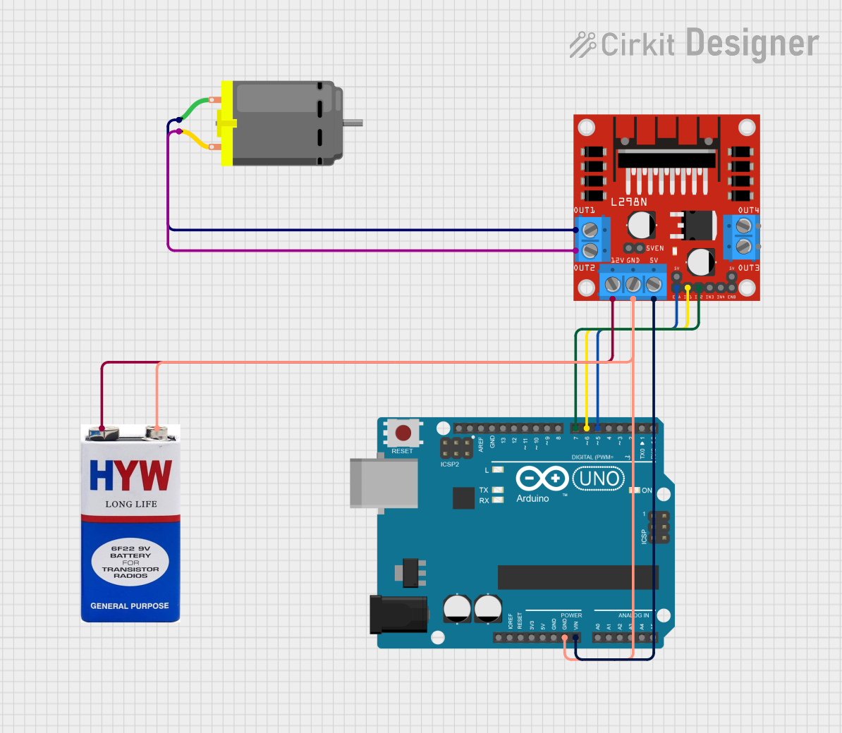
Circuit Documentation
Summary
This circuit is designed to control a DC motor using an Arduino UNO microcontroller and an L298N DC motor driver. The Arduino UNO interfaces with the L298N driver to regulate the direction and speed of the motor. A 9V battery provides the power source for the motor driver and indirectly for the Arduino through voltage regulation.
Component List
Arduino UNO
- Microcontroller board based on the ATmega328P
- It has 14 digital input/output pins, 6 analog inputs, a 16 MHz quartz crystal, a USB connection, a power jack, an ICSP header, and a reset button.
L298N DC Motor Driver
- A module that can control up to two DC motors by adjusting the speed and direction of each independently.
- It has pins for motor power supply, ground, control inputs, and motor outputs.
DC Motor
- An electric motor that runs on direct current (DC) electricity.
- It has two pins for connecting to the motor driver output.
9V Battery
- A standard 9V battery used as the power source.
- It has a positive and a negative terminal for power supply.
Wiring Details
Arduino UNO
- GND connected to the ground of the L298N motor driver and the negative terminal of the 9V battery.
- Vin connected to the 5V output of the L298N motor driver.
- D5 connected to the ENA pin of the L298N motor driver to control motor speed.
- D6 connected to the IN1 pin of the L298N motor driver to control motor direction.
- D7 connected to the IN2 pin of the L298N motor driver to control motor direction.
L298N DC Motor Driver
- GND connected to the negative terminal of the 9V battery and the GND of the Arduino UNO.
- 5V connected to the Vin of the Arduino UNO.
- ENA connected to the D5 of the Arduino UNO for speed control.
- IN1 connected to the D6 of the Arduino UNO for direction control.
- IN2 connected to the D7 of the Arduino UNO for direction control.
- OUT1 connected to pin 1 of the DC Motor.
- OUT2 connected to pin 2 of the DC Motor.
- 12V connected to the positive terminal of the 9V battery.
DC Motor
- Pin 1 connected to OUT1 of the L298N motor driver.
- Pin 2 connected to OUT2 of the L298N motor driver.
9V Battery
- + connected to the 12V input of the L298N motor driver.
- - connected to the GND of the L298N motor driver and the GND of the Arduino UNO.
Documented Code
// Define control pins
int ena = 5; // Enable pin for motor speed
int in1 = 6; // Input pin 1 for motor direction
int in2 = 7; // Input pin 2 for motor direction

// Setup function runs once at startup
void setup() {
  // Initialize the motor control pins as outputs
  pinMode(ena, OUTPUT);
  pinMode(in1, OUTPUT);
  pinMode(in2, OUTPUT);
}

// Loop function runs repeatedly
void loop() {
  // Clockwise rotation at maximum speed
  digitalWrite(in1, HIGH);
  digitalWrite(in2, LOW);
  analogWrite(ena, 255);
  delay(2000);

  // Stop the motor
  digitalWrite(in1, LOW);
  digitalWrite(in2, LOW);
  delay(2000);

  // Counter-clockwise rotation at maximum speed
  digitalWrite(in1, LOW);
  digitalWrite(in2, HIGH);
  analogWrite(ena, 255);
  delay(2000);

  // Stop the motor again
  digitalWrite(in1, LOW);
  digitalWrite(in2, LOW);
  delay(2000);
}
Note: The code provided controls the motor to rotate in one direction at full speed, stop, rotate in the opposite direction at full speed, and then stop again. This cycle repeats indefinitely.