
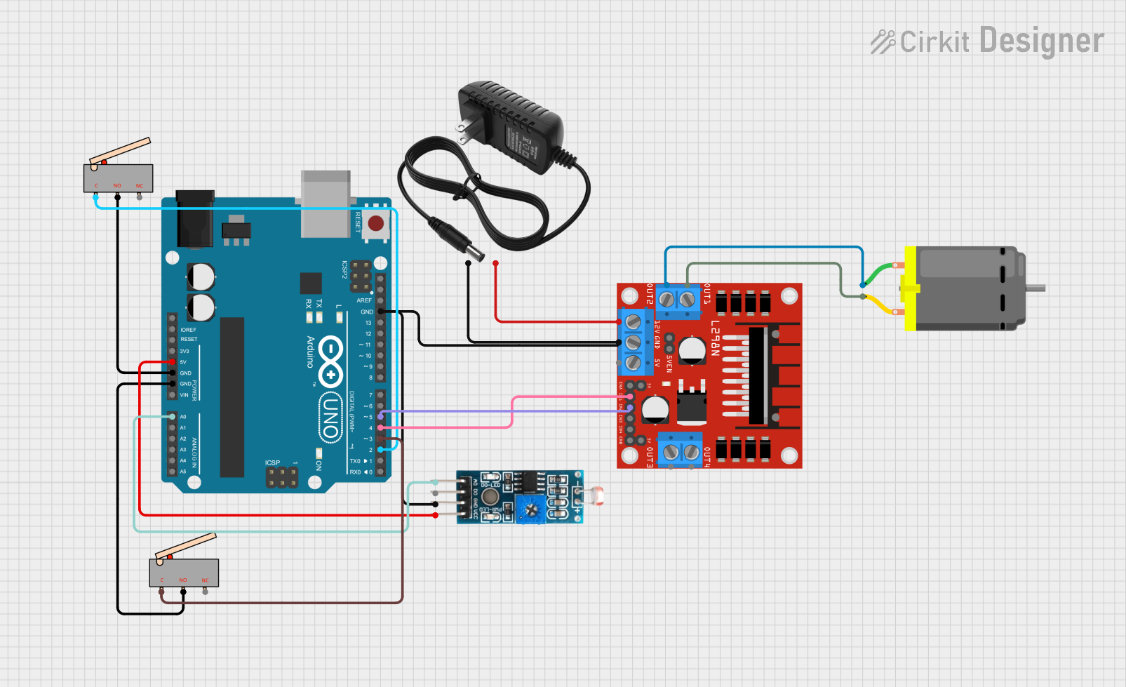
Circuit Documentation
Summary of the Circuit
This circuit is designed around an Arduino UNO microcontroller, which serves as the central processing unit. The circuit includes a Module LDR (Light Dependent Resistor) for light sensing, two limit switches as input devices, a DC motor as an actuator, and an L298N DC motor driver to control the motor. The circuit is powered by a 12V power supply, which provides the necessary voltage for the motor and the motor driver, while the Arduino UNO and the Module LDR are powered by the Arduino's onboard voltage regulators.
Component List
Arduino UNO
- Microcontroller board based on the ATmega328P
- It has 14 digital input/output pins, 6 analog inputs, a 16 MHz quartz crystal, a USB connection, a power jack, an ICSP header, and a reset button.
Limit Switch (x2)
- An electromechanical device that consists of an actuator mechanically linked to a set of contacts.
- When an object comes into contact with the actuator, the device operates the contacts to make or break an electrical connection.
Module LDR
- A light sensor module that includes a Light Dependent Resistor (LDR).
- It has both analog and digital outputs and typically includes a potentiometer to adjust the light sensitivity.
DC Motor
- An electric motor that runs on direct current (DC) electricity.
- It has two terminals for power connection and is controlled by varying voltage or through a motor driver.
L298N DC Motor Driver
- A dual H-Bridge motor driver that can drive two DC motors simultaneously.
- It is capable of driving motors with a voltage between 5V to 35V and can handle peak currents up to 2A per channel.
12V Power Supply
- A power source that provides a stable 12V output.
- It is used to power components in the circuit that require higher voltages, such as the DC motor and the motor driver.
Wiring Details
Arduino UNO
- 5V to Module LDR VCC
- GND to Limit Switch NO (x2), L298N DC motor driver GND, Module LDR GND
- A0 to Module LDR AO
- D5 to L298N DC motor driver IN2
- D4 to L298N DC motor driver IN1
- D3 to Limit Switch C (second switch)
- D2 to Limit Switch C (first switch)
Limit Switches
- NO connected to Arduino UNO GND
- C of the first switch connected to Arduino UNO D2
- C of the second switch connected to Arduino UNO D3
Module LDR
- VCC connected to Arduino UNO 5V
- GND connected to Arduino UNO GND
- AO connected to Arduino UNO A0
DC Motor
- pin 1 connected to L298N DC motor driver OUT2
- pin 2 connected to L298N DC motor driver OUT1
L298N DC Motor Driver
- GND connected to Arduino UNO GND
- IN1 connected to Arduino UNO D4
- IN2 connected to Arduino UNO D5
- OUT1 connected to DC Motor pin 2
- OUT2 connected to DC Motor pin 1
- 12V connected to 12V Power Supply -
12V Power Supply
- + connected to L298N DC motor driver GND
- - connected to L298N DC motor driver 12V
Documented Code
Arduino UNO Code (sketch.ino)
void setup() {
  // put your setup code here, to run once:

}

void loop() {
  // put your main code here, to run repeatedly:

}
The provided code is a template with empty setup() and loop() functions. The setup() function is intended for initialization code that runs once at the start, while the loop() function contains code that runs continuously. Specific functionality needs to be implemented based on the requirements of the circuit's operation.