
Circuit Documentation
Summary
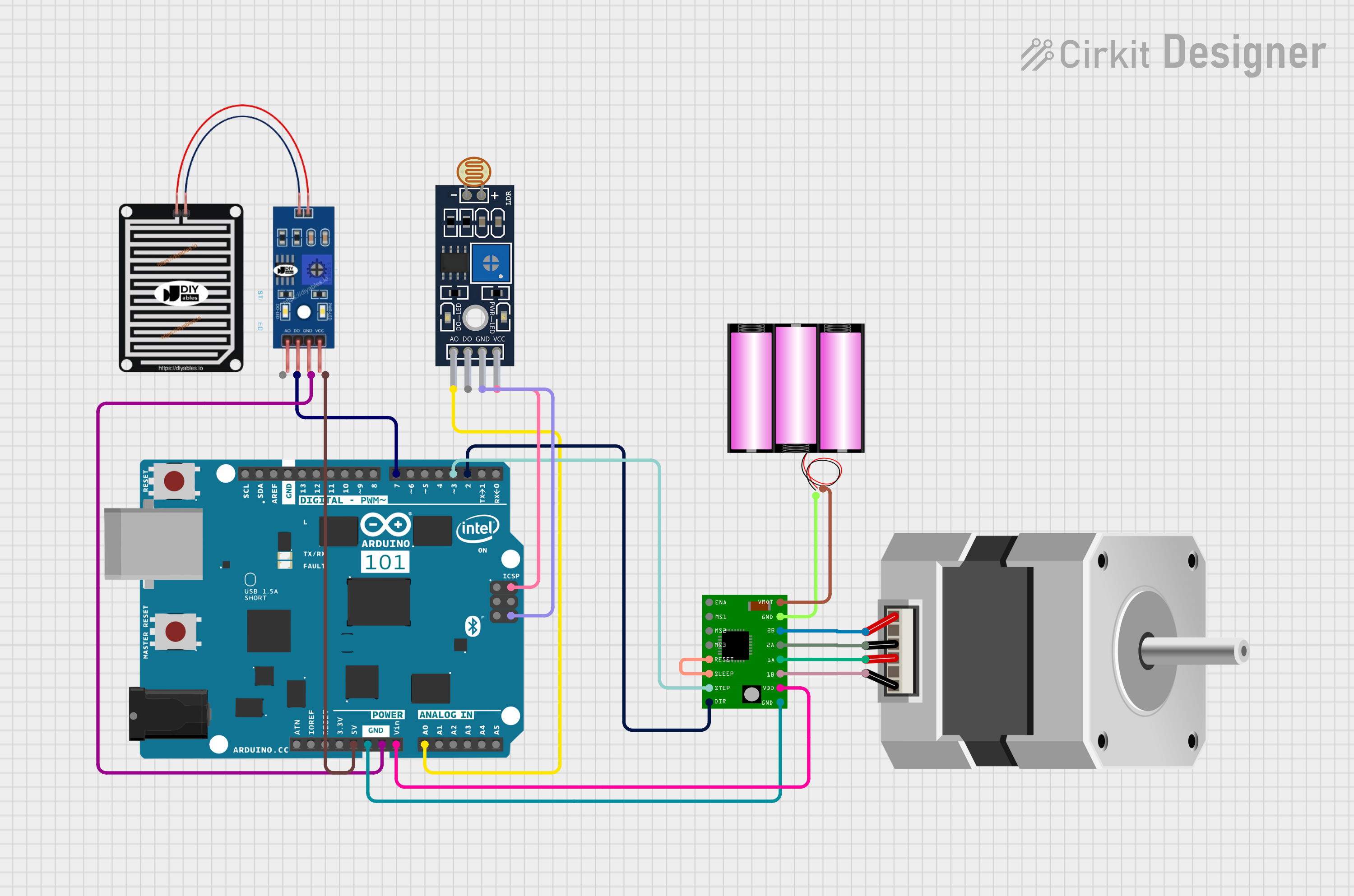
The circuit in question is designed to interface a rain sensor and an LDR (Light Dependent Resistor) sensor with an Arduino 101 microcontroller. Additionally, it controls a bipolar stepper motor using an A4988 Stepper Motor Driver Carrier. The rain sensor is used to detect raindrops and the LDR sensor is used to measure light intensity. The Arduino 101 processes the signals from these sensors and sends commands to the A4988 driver, which in turn drives the stepper motor. The circuit is powered by a 12V battery that supplies power to the motor driver, which also interfaces with the Arduino for control signals.
Component List
RAIN SENSOR
- Pins: AO, DO, GRD, VCC
- Description: A sensor that detects raindrops.
Arduino 101
- Pins: A5/SCL, A4/SDA, AREF, GND, D13/SCK, D12/MISO, D11 PWM/MOSI, D10 PWM/SS, D9 PWM, D8, D7, D6 PWM, D5 PWM, D4, D3 PWM, D2, D1/TX, D0/RX, AIN, ioref, RESET, 3V3, 5V, VIN, A0, A1, A2, A3, ICSP MISO, ICSP SCK, ICSP MOSI
- Description: A microcontroller board based on the Intel Curie module, used for processing sensor data and controlling the stepper motor.
Sensor LDR LM393
- Pins: A0, D0, GND, VCC
- Description: A light sensor module based on the LM393 comparator, used for detecting the intensity of light.
A4988 Stepper Motor Driver Carrier
- Pins: ENABLE, MS1, MS2, MS3, RESET, SLEEP, STEP, DIR, GND, VCC, 1B, 1A, 2A, 2B, VMOT
- Description: A complete micro-stepping motor driver with built-in translator for easy operation.
Stepper Motor (Bipolar)
- Pins: D, B, C, A
- Description: A bipolar stepper motor for precise motion control.
Battery 12V
- Pins: +, -
- Description: A 12V battery providing the power source for the motor driver and the stepper motor.
Wiring Details
RAIN SENSOR
- DO connected to Arduino 101 D7
- GRD connected to Arduino 101 GND
- VCC connected to Arduino 101 5V
Arduino 101
- D7 connected to RAIN SENSOR DO
- GND connected to RAIN SENSOR GRD, Sensor LDR LM393 GND, and A4988 Stepper Motor Driver Carrier GND
- 5V connected to RAIN SENSOR VCC and Sensor LDR LM393 VCC
- VIN connected to A4988 Stepper Motor Driver Carrier VCC
- D3 PWM connected to A4988 Stepper Motor Driver Carrier STEP
- D2 connected to A4988 Stepper Motor Driver Carrier DIR
- A0 connected to Sensor LDR LM393 A0
Sensor LDR LM393
- A0 connected to Arduino 101 A0
- VCC connected to Arduino 101 5V
- GND connected to Arduino 101 GND
A4988 Stepper Motor Driver Carrier
- STEP connected to Arduino 101 D3 PWM
- DIR connected to Arduino 101 D2
- GND connected to Arduino 101 GND and Battery 12V -
- VCC connected to Arduino 101 VIN
- RESET connected to SLEEP
- 1B connected to Stepper Motor (Bipolar) D
- 1A connected to Stepper Motor (Bipolar) B
- 2A connected to Stepper Motor (Bipolar) C
- 2B connected to Stepper Motor (Bipolar) A
- VMOT connected to Battery 12V +
Stepper Motor (Bipolar)
- D connected to A4988 Stepper Motor Driver Carrier 1B
- B connected to A4988 Stepper Motor Driver Carrier 1A
- C connected to A4988 Stepper Motor Driver Carrier 2A
- A connected to A4988 Stepper Motor Driver Carrier 2B
Battery 12V
- + connected to A4988 Stepper Motor Driver Carrier VMOT
- - connected to A4988 Stepper Motor Driver Carrier GND
Documented Code
No code was provided for the microcontroller. The documentation of the code would typically include a description of the functionality, setup, and loop functions, as well as any functions or libraries used to interface with the sensors and motor driver. Since no code is available, this section cannot be completed. If code becomes available, it should be documented here with comments explaining each section and its purpose in the overall operation of the circuit.