
Flame Detection and Intrusion Alert System with Dual Buzzers
View and Edit Project In Cirkit Designer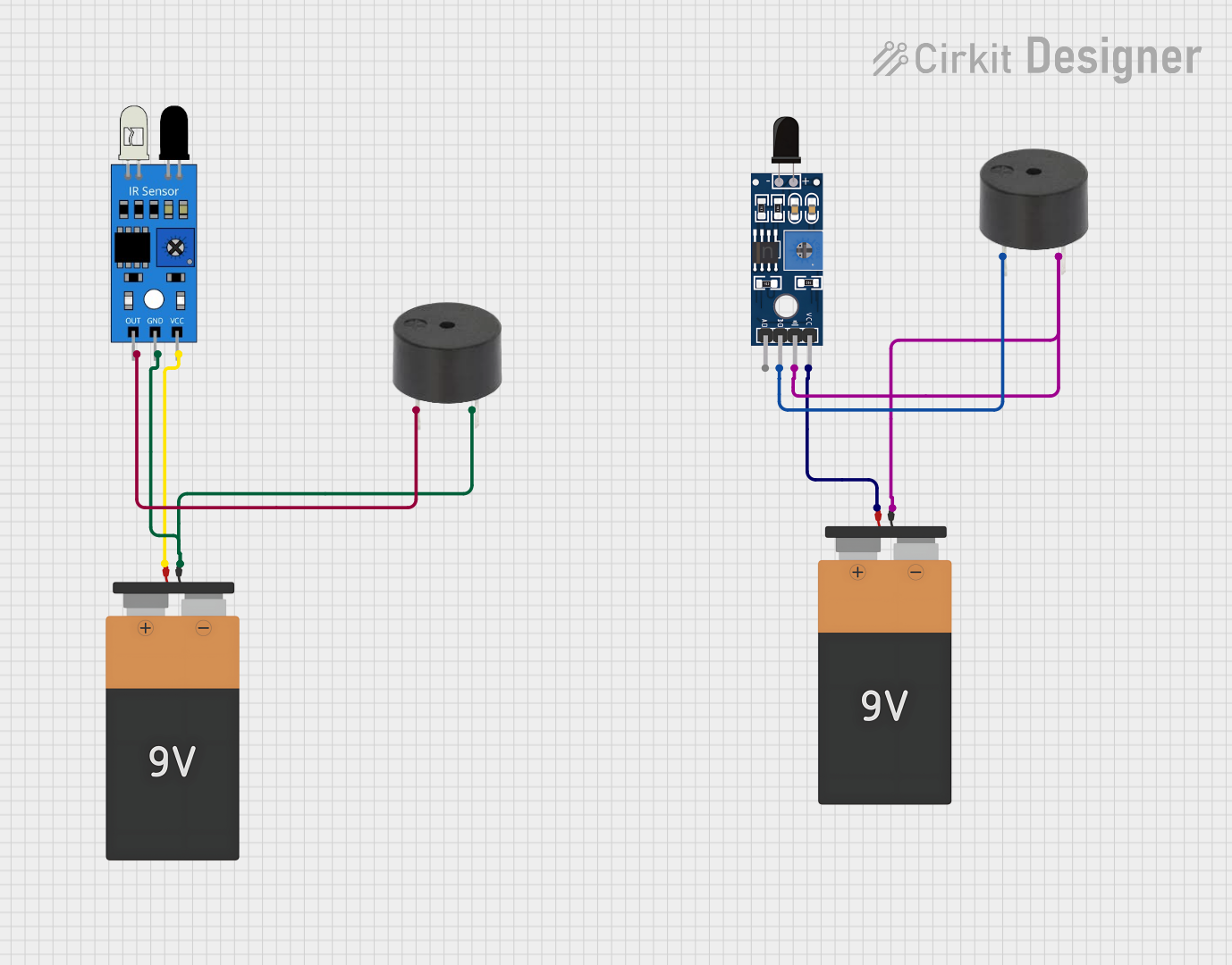
Circuit Documentation
Summary of the Circuit
The circuit in question appears to be a simple sensor and alarm system that utilizes a flame sensor and an infrared (IR) sensor to detect specific conditions and trigger buzzers as alarms. There are two separate subsystems, each consisting of a sensor, a buzzer, and a 9V battery. The flame sensor subsystem is designed to activate a buzzer when a flame is detected, while the IR sensor subsystem is designed to trigger a different buzzer when the IR sensor detects an object or movement.
Component List
Sensor SHT113 Flame
- Description: A flame detection sensor capable of detecting fire or other heat sources.
- Pins: A0 (Analog Output), D0 (Digital Output), GND (Ground), VCC (Power Supply).
Buzzer
- Description: An audible signaling device that emits a tone when powered.
- Pins: PIN (Signal Input), GND (Ground).
Battery 9V
- Description: A standard 9-volt battery providing the power supply for the circuit.
- Pins: VCC (Positive Terminal), GND (Negative Terminal).
IR Sensor
- Description: An infrared sensor used for detecting presence or movement.
- Pins: out (Signal Output), gnd (Ground), vcc (Power Supply).
Wiring Details
Sensor SHT113 Flame
- D0: Connected to the PIN of the first buzzer.
- GND: Shared ground with the first buzzer and the first 9V battery.
- VCC: Connected to the VCC of the first 9V battery.
Buzzer (First Instance)
- PIN: Connected to the D0 of the flame sensor.
- GND: Shared ground with the flame sensor and the first 9V battery.
Battery 9V (First Instance)
- VCC: Connected to the VCC of the flame sensor.
- GND: Shared ground with the flame sensor and the first buzzer.
IR Sensor
- out: Connected to the PIN of the second buzzer.
- gnd: Shared ground with the second buzzer and the second 9V battery.
- vcc: Connected to the VCC of the second 9V battery.
Buzzer (Second Instance)
- PIN: Connected to the out of the IR sensor.
- GND: Shared ground with the IR sensor and the second 9V battery.
Battery 9V (Second Instance)
- VCC: Connected to the VCC of the IR sensor.
- GND: Shared ground with the IR sensor and the second buzzer.
Documented Code
There is no embedded code provided for any microcontrollers in this circuit. If the circuit is intended to operate solely on the basis of the sensors' outputs without any additional logic or processing, then no microcontroller or embedded code is necessary. However, if there is a need for more complex behavior, a microcontroller and associated code would be required.