
Transistor-Based Signal Modulation Circuit with AC/DC Power Integration
View and Edit Project In Cirkit Designer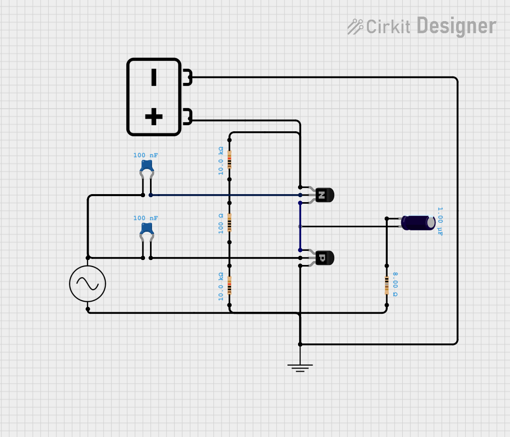
Circuit Documentation
Summary of the Circuit
The circuit in question appears to be a combination of passive and active components, including resistors, capacitors, transistors, a battery, and an AC supply. The circuit does not include any microcontroller code, suggesting that it is purely analog in nature. The components are interconnected to form a network that could serve various purposes such as signal amplification, filtering, or power regulation. The exact function of the circuit is not specified, but the presence of transistors indicates that some form of control or switching is involved.
Component List
12v Battery
- Description: A 12-volt battery providing the DC power supply to the circuit.
Resistor (10k Ohms)
- Description: A resistor with a resistance of 10,000 Ohms.
Resistor (100 Ohms)
- Description: A resistor with a resistance of 100 Ohms.
Resistor (10k Ohms)
- Description: Another resistor with a resistance of 10,000 Ohms, identical to the first one.
Resistor (8 Ohms)
- Description: A resistor with a resistance of 8 Ohms.
Ceramic Capacitor (0.1 µF)
- Description: A ceramic capacitor with a capacitance of 0.1 microfarads.
PNP Transistor (EBC)
- Description: A PNP transistor with emitter, base, and collector pins.
NPN Transistor (CBE)
- Description: An NPN transistor with collector, base, and emitter pins.
GND (Ground)
- Description: A ground reference point for the circuit.
AC Supply
- Description: An alternating current supply source.
Ceramic Capacitor (0.1 µF)
- Description: Another ceramic capacitor with a capacitance of 0.1 microfarads, identical to the first one.
Electrolytic Capacitor (1 µF)
- Description: An electrolytic capacitor with a capacitance of 1 microfarad.
Wiring Details
12v Battery
- Positive terminal connected to the collector of the NPN transistor.
- Negative terminal connected to the ground, collector of the PNP transistor, and one end of a 10k Ohm resistor.
Resistor (10k Ohms)
- One end connected to the negative terminal of the 12v battery.
- The other end connected to another 10k Ohm resistor.
Resistor (100 Ohms)
- One end connected to the positive terminal of the 12v battery.
- The other end connected to a 100 Ohm resistor.
Resistor (10k Ohms)
- One end connected to a 10k Ohm resistor.
- The other end connected to the ground.
Resistor (8 Ohms)
- One end connected to the ground.
- The other end connected to the negative terminal of an electrolytic capacitor.
Ceramic Capacitor (0.1 µF)
- One end connected to the AC supply's positive terminal and another ceramic capacitor.
- The other end connected to the base of the PNP transistor.
PNP Transistor (EBC)
- Emitter connected to the ground and the emitter of the NPN transistor.
- Base connected to a ceramic capacitor.
- Collector connected to the ground.
NPN Transistor (CBE)
- Collector connected to the positive terminal of the 12v battery.
- Base connected to a ceramic capacitor.
- Emitter connected to the emitter of the PNP transistor.
GND (Ground)
- Connected to the negative terminal of the AC supply, one end of an 8 Ohm resistor, the collector of the PNP transistor, and one end of a 10k Ohm resistor.
AC Supply
- Positive terminal connected to a ceramic capacitor.
- Negative terminal connected to the ground.
Ceramic Capacitor (0.1 µF)
- One end connected to the AC supply's positive terminal and another ceramic capacitor.
- The other end connected to the base of the NPN transistor.
Electrolytic Capacitor (1 µF)
- Positive terminal unconnected.
- Negative terminal connected to one end of an 8 Ohm resistor.
Documented Code
There is no embedded code provided for this circuit as it does not include any programmable components or microcontrollers. The circuit operates purely on the basis of its analog components and their interconnections.