
Arduino UNO Controlled PIR Motion Sensor with Relay and Contactor for 220V Fan Automation
View and Edit Project In Cirkit Designer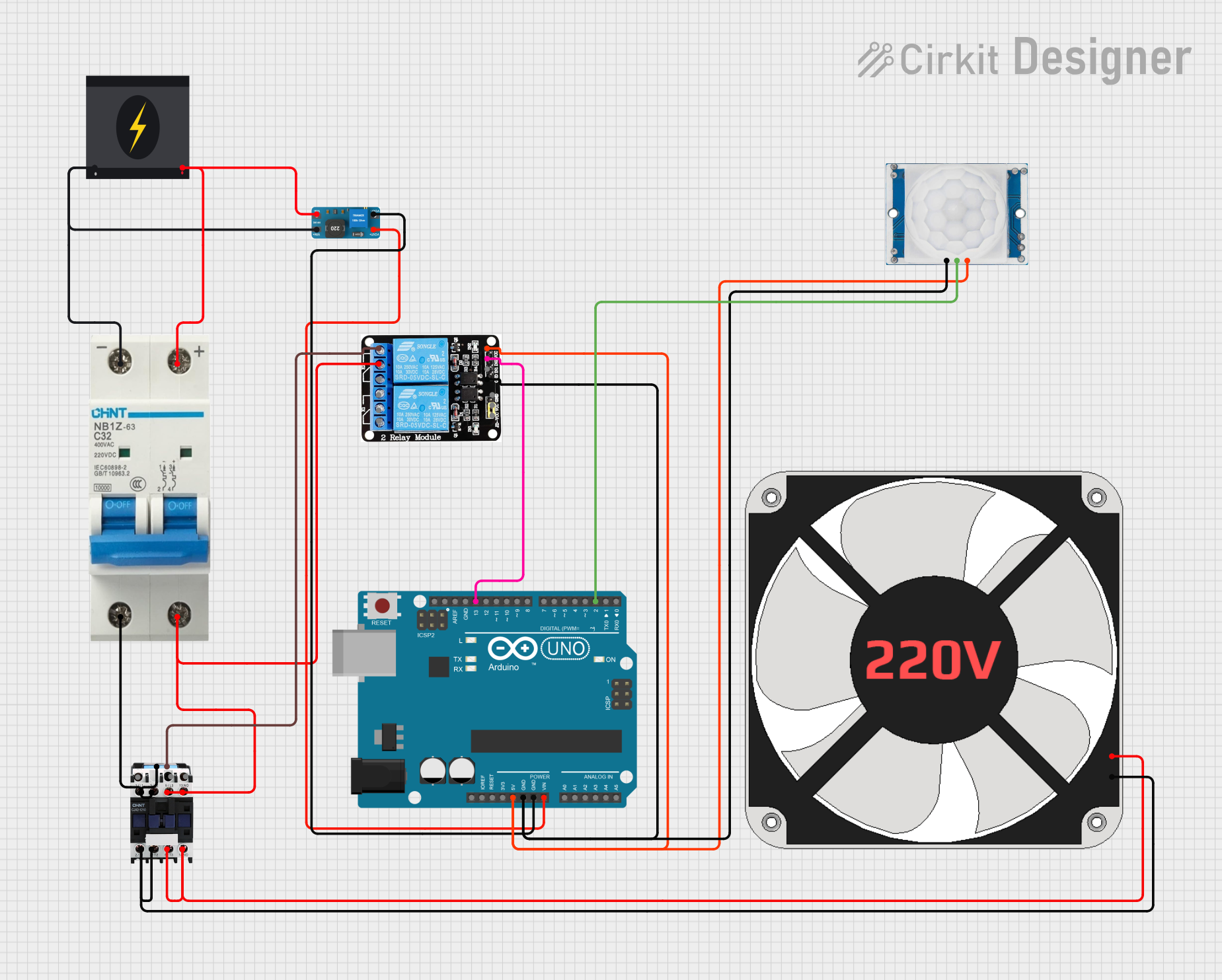
Circuit Documentation
Summary
This circuit integrates an Arduino UNO microcontroller with a variety of components including a HC-SR501 PIR motion sensor, a 5V 2-Relay module, a circuit breaker, a magnetic contactor, a 240V power source, a DC to DC boost converter, and a 220V fan. The Arduino UNO is used as the central control unit, interfacing with the motion sensor and controlling the relay, which in turn manages power to the magnetic contactor and the fan. The circuit breaker provides overcurrent protection, and the power source supplies the necessary voltage to the system. The DC to DC boost converter steps up the voltage to meet the Arduino's input voltage requirements.
Component List
Arduino UNO
- Microcontroller board based on the ATmega328P
- Provides digital and analog I/O pins
- Can be powered via USB or external power supply
HC-SR501 PIR Motion Sensor
- Passive infrared sensor that detects motion
- Operates at 5V and provides a digital output
5V 2-Relay JD-VCC
- Relay module with two channels
- Allows for control of high power devices
Circuit Breaker
- Safety device that automatically interrupts current flow in case of overload
Magnetic Contactor
- Electrically controlled switch used for switching an electrical power circuit
240V Power Source
- Provides the main AC power for the circuit
DC to DC Boost Converter
- Steps up voltage from a lower voltage to a higher voltage
220V Fan
- Standard fan operating at 220V for cooling or ventilation purposes
Wiring Details
Arduino UNO
5Vconnected to Relay VCC and PIR motion sensor Power SupplyGNDconnected to Relay GND, PIR motion sensor Ground, and DC to DC boost converter out-Vinconnected to DC to DC boost converter out+D13connected to Relay IN2D2connected to PIR motion sensor Output
HC-SR501 PIR Motion Sensor
Outputconnected to Arduino UNO D2Groundconnected to Arduino UNO GNDPower Supplyconnected to Arduino UNO 5V
5V 2-Relay JD-VCC
VCCconnected to Arduino UNO 5VGNDconnected to Arduino UNO GNDIN2connected to Arduino UNO D13NOconnected to Magnetic Contactor powerCOMconnected to Magnetic Contactor 5/L3, 13 NO, and Circuit Breaker +
Circuit Breaker
+connected to Relay COM and 240V Power Source Live-connected to Magnetic Contactor 1/L1, 3/L2, power, and DC to DC boost converter vin-
Magnetic Contactor
powerconnected to Relay NO5/L3and13 NOconnected to Relay COM1/L1and3/L2connected to Circuit Breaker -2/T1and4/T2connected to 220V Fan N6/T3and14 NOconnected to 220V Fan L
240V Power Source
Liveconnected to Circuit Breaker +Neutralconnected to Circuit Breaker -, DC to DC boost converter vin-
DC to DC Boost Converter
vin-connected to Circuit Breaker - and 240V Power Source Neutralvin+connected to Circuit Breaker +out+connected to Arduino UNO Vinout-connected to Arduino UNO GND
220V Fan
Nconnected to Magnetic Contactor 2/T1, 4/T2Lconnected to Magnetic Contactor 6/T3, 14 NO
Documented Code
Arduino UNO Code (sketch.ino)
void setup() {
  // put your setup code here, to run once:

}

void loop() {
  // put your main code here, to run repeatedly:

}
Note: The provided code is a template and does not include specific functionality. It should be populated with the necessary setup and loop code to control the relay based on the PIR sensor output and any other required logic.