
Arduino Nano-Based GPS and GSM Tracker with RGB LED Indicators
View and Edit Project In Cirkit Designer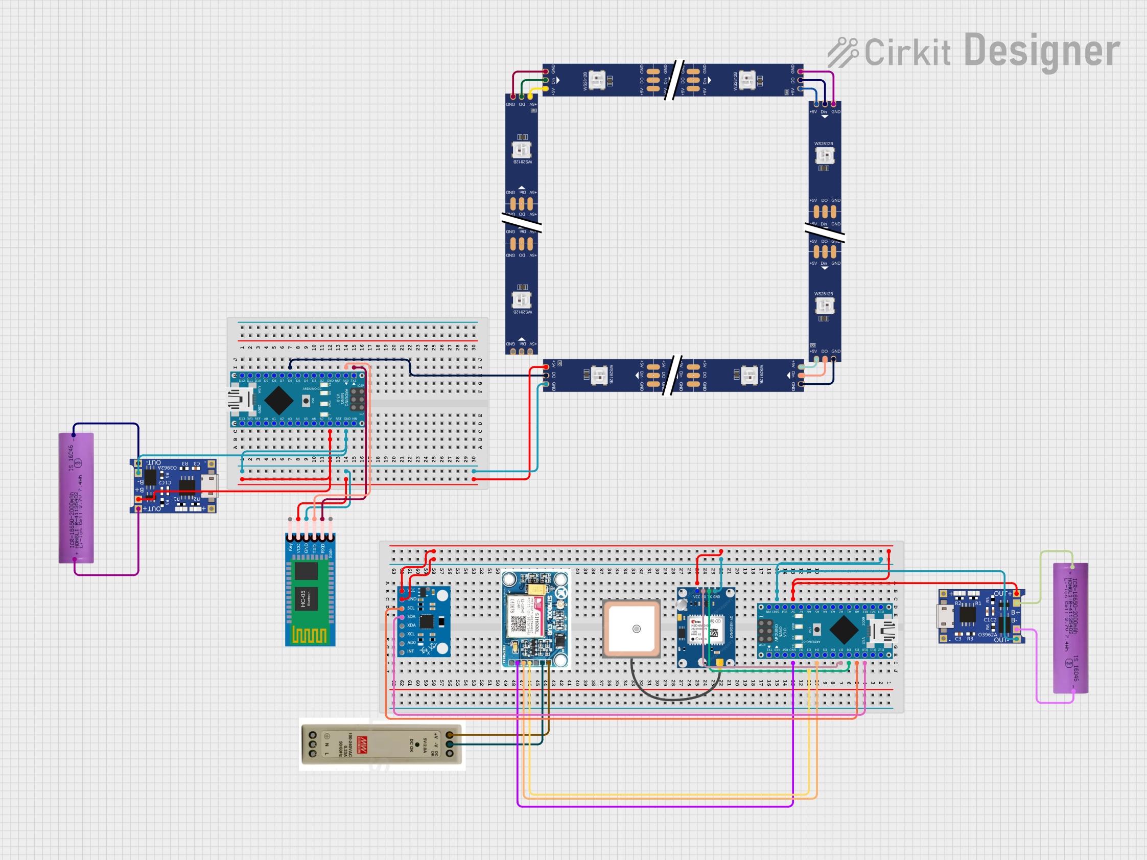
Circuit Documentation
Summary
This document provides a detailed overview of a circuit that integrates various components including Arduino Nano microcontrollers, a GPS module, an MPU6050 sensor, WS2812 RGB LED strips, a SIM 800L GSM module, a Bluetooth module, a power supply unit, and Li-ion batteries. The circuit is designed to perform multiple functions such as GPS tracking, motion sensing, and wireless communication.
Component List
Arduino Nano
- Description: A small, complete, and breadboard-friendly board based on the ATmega328P.
- Pins: D1/TX, D0/RX, RESET, GND, D2, D3, D4, D5, D6, D7, D8, D9, D10, D11/MOSI, D12/MISO, VIN, 5V, A7, A6, A5, A4, A3, A2, A1, A0, AREF, 3V3, D13/SCK
GPS NEO 6M
- Description: A GPS module used for tracking and navigation.
- Pins: VCC, RX, TX, GND
WS2812 RGB LED strip
- Description: An addressable RGB LED strip.
- Pins: DIN, 5V, GND, DO
MPU6050
- Description: A 6-axis motion tracking device that combines a 3-axis gyroscope and a 3-axis accelerometer.
- Pins: vcc, gnd, scl, sda, xda, xcl, AD0, int, 3.3v
SIM 800L V2.0 GSM
- Description: A GSM module for wireless communication.
- Pins: SIM_TXD, VDD, SIM.RXD, 5V/4V, GND, RST
HC-05 Bluetooth Module
- Description: A Bluetooth module for wireless communication.
- Pins: Key, VCC, TXD, RXD, State, GND
5V PSU
- Description: A 5V power supply unit.
- Pins: 5V+, GND, 5V OK, PE, N, L
Li-ion battery 18650-2000mAh 3.7V 7.4WH
- Description: A rechargeable Li-ion battery.
- Pins: +, -
TP4056
- Description: A lithium battery charger module.
- Pins: OUT-, B-, B+, OUT+, IN-, IN+
Wiring Details
Arduino Nano
- D10 connected to MPU6050 sda
- D9 connected to MPU6050 scl
- D8 connected to GPS NEO 6M TX
- D7 connected to GPS NEO 6M RX
- D4 connected to SIM 800L V2.0 GSM SIM.RXD
- D3 connected to SIM 800L V2.0 GSM SIM_TXD
- 5V connected to TP4056 OUT+, GPS NEO 6M VCC, MPU6050 vcc, WS2812 RGB LED strip 5V, HC-05 Bluetooth Module VCC
- GND connected to TP4056 OUT-, GPS NEO 6M GND, MPU6050 gnd, SIM 800L V2.0 GSM GND, WS2812 RGB LED strip GND, HC-05 Bluetooth Module GND
GPS NEO 6M
- TX connected to Arduino Nano D8
- RX connected to Arduino Nano D7
- VCC connected to Arduino Nano 5V
- GND connected to Arduino Nano GND
WS2812 RGB LED strip
- DIN connected to WS2812 RGB LED strip DO
- 5V connected to Arduino Nano 5V
- GND connected to Arduino Nano GND
- DO connected to WS2812 RGB LED strip DIN
MPU6050
- sda connected to Arduino Nano D10
- scl connected to Arduino Nano D9
- vcc connected to Arduino Nano 5V
- gnd connected to Arduino Nano GND
SIM 800L V2.0 GSM
- SIM.RXD connected to Arduino Nano D4
- SIM_TXD connected to Arduino Nano D3
- 5V/4V connected to 5V PSU 5V+
- GND connected to 5V PSU GND
HC-05 Bluetooth Module
- TXD connected to Arduino Nano D0/RX
- RXD connected to Arduino Nano D1/TX
- VCC connected to Arduino Nano 5V
- GND connected to Arduino Nano GND
5V PSU
- 5V+ connected to SIM 800L V2.0 GSM 5V/4V
- GND connected to SIM 800L V2.0 GSM GND
Li-ion battery 18650-2000mAh 3.7V 7.4WH
- + connected to TP4056 B+
- - connected to TP4056 B-
TP4056
- OUT+ connected to Arduino Nano 5V
- OUT- connected to Arduino Nano GND
- B+ connected to Li-ion battery 18650-2000mAh 3.7V 7.4WH +
- B- connected to Li-ion battery 18650-2000mAh 3.7V 7.4WH -
Documented Code
Arduino Nano (Instance 1)
File Name: sketch.ino
void setup() {
  // put your setup code here, to run once:

}

void loop() {
  // put your main code here, to run repeatedly:

}
Arduino Nano (Instance 2)
File Name: sketch.ino
void setup() {
  // put your setup code here, to run once:

}

void loop() {
  // put your main code here, to run repeatedly:

}
This documentation provides a comprehensive overview of the circuit, including the components used, their wiring details, and the code for the microcontrollers.