
Wi-Fi Controlled DC Motor System using ESP32 and L298N Driver
View and Edit Project In Cirkit Designer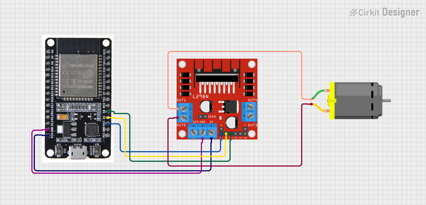
Circuit Documentation
Summary
This circuit consists of an ESP32 microcontroller, an L298N DC motor driver, and a DC motor. The ESP32 controls the L298N motor driver, which in turn drives the DC motor. The circuit is powered through the ESP32, which is connected to the L298N motor driver for power and ground.
Component List
ESP32
- Description: A powerful microcontroller with built-in Wi-Fi and Bluetooth capabilities.
- Pins: EN, VP, VN, D34, D35, D32, D33, D25, D26, D27, D14, D12, D13, GND, VIN, 3V3, D15, D2, D4, RX2, TX2, D5, D18, D19, D21, RX0, TX0, D22, D23, BOOT
L298N DC Motor Driver
- Description: A dual H-bridge motor driver that allows control of the speed and direction of two DC motors.
- Pins: OUT1, OUT2, 12V, GND, 5V, OUT3, OUT4, 5V-ENA-JMP-I, 5V-ENA-JMP-O, +5V-J1, +5V-J2, ENA, IN1, IN2, IN3, IN4, ENB
DC Motor
- Description: A simple DC motor used for various applications.
- Pins: pin 1, pin 2
Wiring Details
ESP32
- GND: Connected to GND of L298N DC motor driver
- VIN: Connected to 5V of L298N DC motor driver
- D15: Connected to ENA of L298N DC motor driver
- D2: Connected to IN1 of L298N DC motor driver
- D4: Connected to IN2 of L298N DC motor driver
L298N DC Motor Driver
- GND: Connected to GND of ESP32
- 5V: Connected to VIN of ESP32
- ENA: Connected to D15 of ESP32
- IN1: Connected to D2 of ESP32
- IN2: Connected to D4 of ESP32
- OUT1: Connected to pin 1 of DC Motor
- OUT2: Connected to pin 2 of DC Motor
DC Motor
- pin 1: Connected to OUT1 of L298N DC motor driver
- pin 2: Connected to OUT2 of L298N DC motor driver
Code
There is no code provided for this circuit.