Cirkit Designer
Your all-in-one circuit design IDE
Home /
Project Documentation
Arduino UNO RFID Attendance System with Real-Time Clock and LCD Display
Circuit Documentation
Summary
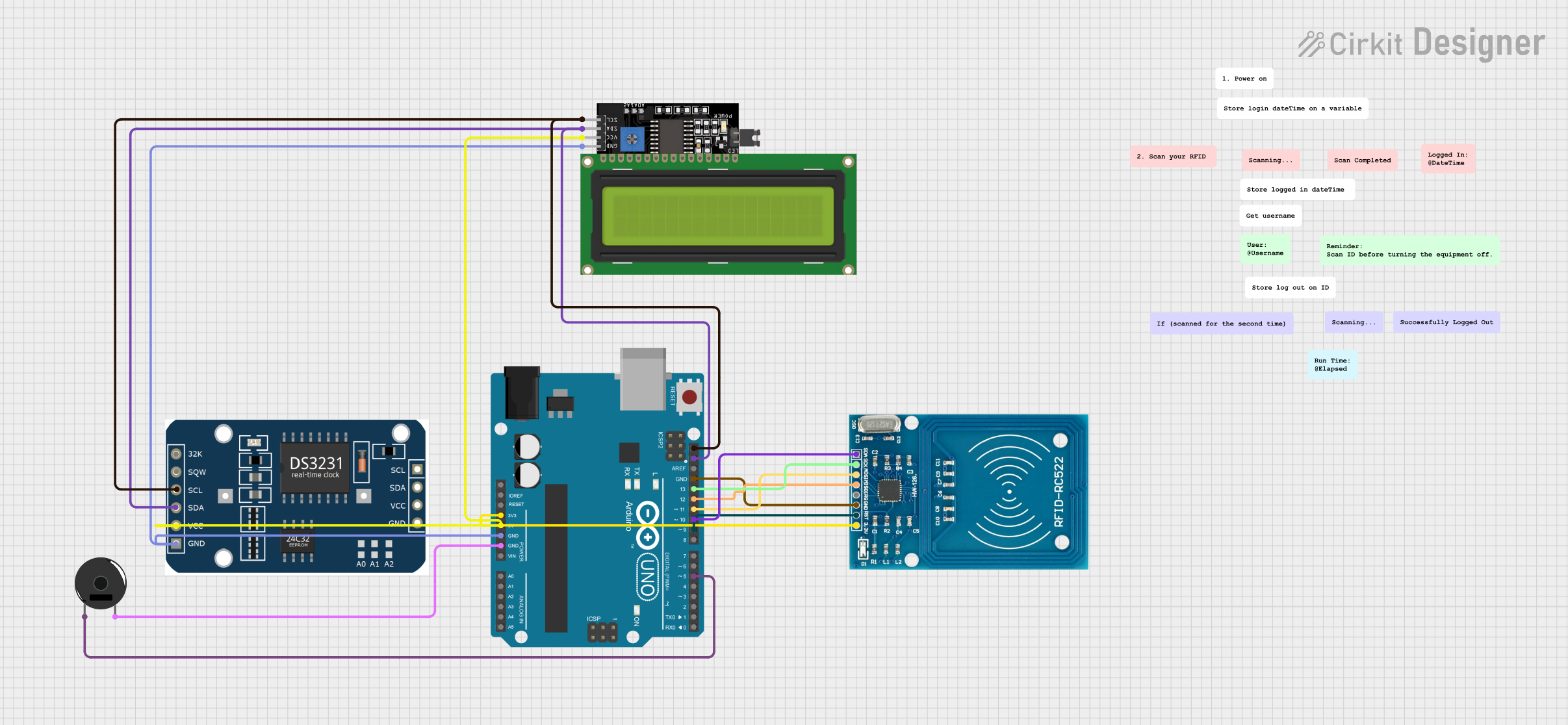
This document provides a detailed overview of a circuit designed to interface an Arduino UNO with an RFID reader, an LCD display, an RTC module, and a piezo buzzer. The circuit is intended to log and display login and logout times, and it includes a button to trigger the logout process. The Arduino UNO serves as the central microcontroller, coordinating the operations of the connected components.
Component List
Arduino UNO
- Description: A microcontroller board based on the ATmega328P.
- Pins: UNUSED, IOREF, Reset, 3.3V, 5V, GND, Vin, A0, A1, A2, A3, A4, A5, SCL, SDA, AREF, D13, D12, D11, D10, D9, D8, D7, D6, D5, D4, D3, D2, D1, D0
RFID-RC522
- Description: An RFID reader module.
- Pins: VCC (3.3V), RST, GND, IRQ, MISO, MOSI, SCK, SDA
LCD Display 16x4 I2C
- Description: A 16x4 character LCD display with I2C interface.
- Pins: SCL, SDA, VCC, GND
rtc MODULE
- Description: A Real-Time Clock (RTC) module.
- Pins: 32k, SQW, SCL, SDA, VCC, GND
Piezo Buzzer
- Description: A simple piezoelectric buzzer.
- Pins: pin 1, pin 2
Wiring Details
Arduino UNO
- 3.3V connected to RFID-RC522 VCC (3.3V)
- D9 connected to RFID-RC522 RST
- GND connected to RFID-RC522 GND
- D12 connected to RFID-RC522 MISO
- D11 connected to RFID-RC522 MOSI
- D13 connected to RFID-RC522 SCK
- D10 connected to RFID-RC522 SDA
- SCL connected to LCD Display 16x4 I2C SCL and rtc MODULE SCL
- SDA connected to LCD Display 16x4 I2C SDA and rtc MODULE SDA
- 5V connected to LCD Display 16x4 I2C VCC and rtc MODULE VCC
- GND connected to LCD Display 16x4 I2C GND and rtc MODULE GND
- D5 connected to Piezo Buzzer pin 1
- GND connected to Piezo Buzzer pin 2
RFID-RC522
- VCC (3.3V) connected to Arduino UNO 3.3V
- RST connected to Arduino UNO D9
- GND connected to Arduino UNO GND
- MISO connected to Arduino UNO D12
- MOSI connected to Arduino UNO D11
- SCK connected to Arduino UNO D13
- SDA connected to Arduino UNO D10
LCD Display 16x4 I2C
- SCL connected to Arduino UNO SCL and rtc MODULE SCL
- SDA connected to Arduino UNO SDA and rtc MODULE SDA
- VCC connected to Arduino UNO 5V and rtc MODULE VCC
- GND connected to Arduino UNO GND and rtc MODULE GND
rtc MODULE
- SCL connected to Arduino UNO SCL and LCD Display 16x4 I2C SCL
- SDA connected to Arduino UNO SDA and LCD Display 16x4 I2C SDA
- VCC connected to Arduino UNO 5V and LCD Display 16x4 I2C VCC
- GND connected to Arduino UNO GND and LCD Display 16x4 I2C GND
Piezo Buzzer
- pin 1 connected to Arduino UNO D5
- pin 2 connected to Arduino UNO GND
Code Documentation
Main Code
#include <Wire.h>
#include <RTClib.h>
#include <LiquidCrystal_I2C.h>

// Initialize the LCD display with I2C address 0x27 and size 16x2
LiquidCrystal_I2C lcd(0x27, 16, 2);

// Initialize the RTC module
RTC_DS3231 rtc;

// Variables to store login and logout times
DateTime loggedIn;
DateTime loggedOut;

// Variable to store the period (AM/PM)
String period = "AM";

// Pin definitions
const byte BUZZER_PIN = 5;  // You can use any available digital pin
const byte BUTTON_PIN = 3;   // Ensure this pin is available on the Uno

// Variables to track button state
byte lastState = LOW;  // Previous state of the button
int currentState;      // Current state of the button

void setup() {
  // Start the I2C communication
  Wire.begin();

  // Set pin modes
  pinMode(BUZZER_PIN, OUTPUT);
  pinMode(BUTTON_PIN, INPUT_PULLUP);

  // Initialize serial communication at 9600 bits per second
  Serial.begin(9600);

  // Initialize the LCD display
  lcd.init();
  lcd.backlight();

  // Initialize the RTC module
  if (!rtc.begin()) {
    Serial.print("Couldn't find RTC");
    Serial.flush();
    while (1);
  }

  // Check if the RTC lost power and set the time if necessary
  if (rtc.lostPower()) {
    Serial.println("RTC lost power, let's set the time!");
    rtc.adjust(DateTime(F(__DATE__), F(__TIME__)));
  }

  // Display the login time on the LCD
  lcd.clear();
  lcd.print("Logged In:");
  loggedIn = rtc.now();
  displayTime(loggedIn);
}

void loop() {
  // Read the state of the button
  currentState = digitalRead(BUTTON_PIN);

  // Check for button press (transition from HIGH to LOW)
  if (lastState == HIGH && currentState == LOW) {
    // Sound the buzzer
    tone(BUZZER_PIN, 2000); // Send a 2kHz sound signal
    delay(500);             // for 0.5 seconds
    noTone(BUZZER_PIN);     // Stop the tone

    // Display the logout time on the LCD
    lcd.clear();
    lcd.print("Logged Out:");
    loggedOut = rtc.now();
    displayTime(loggedOut);

    delay(3000);
    lcd.clear();

    // Calculate and display the elapsed time
    long elapsedSeconds = loggedOut.unixtime() - loggedIn.unixtime();
    int elapsedHours = elapsedSeconds / 3600;
    int elapsedMinutes = (elapsedSeconds % 3600) / 60;
    int elapsedSecondsRemaining = elapsedSeconds % 60;

    lcd.print("Elapsed time:");
    lcd.setCursor(0, 1);
    lcd.print(elapsedHours);
    lcd.print("h ");
    lcd.print(elapsedMinutes);
    lcd.print("m ");
    lcd.print(elapsedSecondsRemaining);
    lcd.print("s");

    delay(5000);
    lcd.clear();
  }

  // Update the last state of the button
  lastState = currentState;
}

// Function to display time on the LCD
void displayTime(DateTime time) {
  lcd.setCursor(0, 1);
  int hour = time.hour();
  if (hour >= 12) {
    period = "PM";
    if (hour > 12) {
      hour -= 12;
    }
  } else if (hour == 0) {
    hour = 12;
  }
  lcd.print(hour);
  lcd.print(':');
  if (time.minute() < 10) lcd.print('0'); // Leading zero for minutes
  lcd.print(time.minute());
  lcd.print(':');
  if (time.second() < 10) lcd.print('0'); // Leading zero for seconds
  lcd.print(time.second());
  lcd.print(' ');
  lcd.print(period);
}
Additional Code
#include <Wire.h>
#include <RTClib.h>
#include <LiquidCrystal_I2C.h>

// Initialize the LCD display with I2C address 0x27 and size 16x2
LiquidCrystal_I2C lcd(0x27, 16, 2);

// Initialize the RTC module
RTC_DS3231 rtc;

// Variables to store login and logout times
DateTime loggedIn;
DateTime loggedOut;

// Variable to store the period (AM/PM)
String period = "AM";

// Pin definitions
const byte BUZZER_PIN = 5;  // You can use any available digital pin
const byte BUTTON_PIN = 3;   // Ensure this pin