
Arduino-Controlled 8-LED Pattern Display with 74HC595 Shift Register
View and Edit Project In Cirkit Designer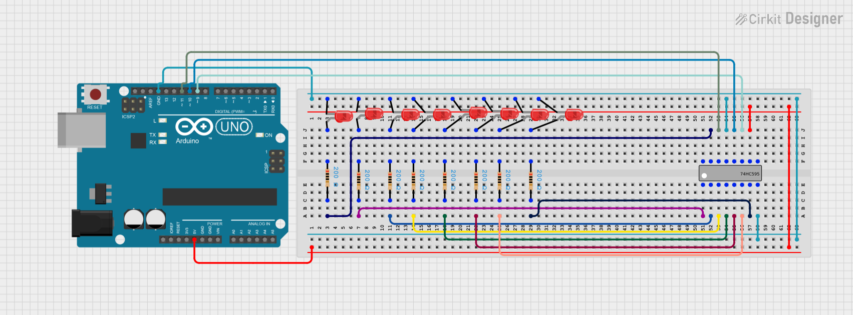
Circuit Documentation
Summary
This circuit utilizes an Arduino UNO microcontroller to control a 74HC595 shift register, which in turn drives multiple LEDs. The LEDs are arranged to display alternating patterns, with resistors in series to limit the current. The shift register expands the output capabilities of the Arduino, allowing for control of multiple LEDs with only a few pins. The circuit is designed to alternate between two LED patterns with a specified delay.
Component List
LEDs
- LED: Two Pin (red): Standard red LEDs used for visual output. Each LED has an anode and cathode pin.
Resistors
- Resistor: These are 200 Ohm resistors used to limit the current through the LEDs to prevent damage.
Microcontroller
- Arduino UNO: A microcontroller board based on the ATmega328P. It has digital input/output pins, analog inputs, and various power pins.
Shift Register
- 74HC595: An 8-bit shift register with output latches. It has 8 output pins (Q0-Q7), serial data input (DS), output enable (OE), a latch pin (ST_CP), a clock pin (SH_CP), and a master reset (MR).
Wiring Details
Arduino UNO
- Digital Pins: D9, D10, D11 are used to control the 74HC595 shift register.
- Power Pins: 5V and GND are used to power the 74HC595 and the common cathode of the LEDs.
74HC595 Shift Register
- Q0-Q7: Connected to the anode of LEDs through 200 Ohm resistors.
- DS (DATA): Connected to Arduino's D11 (dataPin).
- OE (Enable): Connected to the common cathode of the LEDs and Arduino's GND.
- ST_CP (RCLK): Connected to Arduino's D10 (latchPin).
- SH_CP (SRCLK): Connected to Arduino's D9 (clockPin).
- MR (SRCLR): Connected to Arduino's 5V to keep the register from resetting.
- GND: Connected to Arduino's GND.
- VCC: Powered by Arduino's 5V pin.
LEDs
- Anode: Connected to the Q0-Q7 outputs of the 74HC595 through 200 Ohm resistors.
- Cathode: Common cathode connected to the OE (Enable) of the 74HC595 and Arduino's GND.
Resistors
- 200 Ohm: Each resistor is connected in series with an LED between the anode and the corresponding Q0-Q7 output of the 74HC595.
Documented Code
/*
 * This Arduino sketch controls a 74HC595 shift register to drive multiple LEDs.
 * The LEDs will alternate between two patterns, with a delay between each pattern.
 * The shift register is controlled via three pins: latch, clock, and data.
 */

int latchPin = 10; // Pin connected to ST_CP of 74HC595
int clockPin = 9;  // Pin connected to SH_CP of 74HC595
int dataPin = 11;  // Pin connected to DS of 74HC595
int dt = 250;      // Delay time between LED patterns

byte LED1s = 0b10101010; // First LED pattern
byte LED2s = 0b01010101; // Second LED pattern

void setup() {
  // Initialize serial communication
  Serial.begin(9600);
  // Set the latch, clock, and data pins as outputs
  pinMode(latchPin, OUTPUT);
  pinMode(clockPin, OUTPUT);
  pinMode(dataPin, OUTPUT);
}

void loop() {
  // Send the first LED pattern to the shift register
  digitalWrite(latchPin, LOW);
  shiftOut(dataPin, clockPin, LSBFIRST, LED1s);
  digitalWrite(latchPin, HIGH);
  delay(dt);
  // Send the second LED pattern to the shift register
  digitalWrite(latchPin, LOW);
  shiftOut(dataPin, clockPin, LSBFIRST, LED2s);
  digitalWrite(latchPin, HIGH);
  delay(dt);
}
This code is designed to run on the Arduino UNO microcontroller. It initializes the pins connected to the 74HC595 shift register and alternates between two LED patterns with a delay specified by the dt variable. The shiftOut function is used to send the pattern to the shift register, which then updates the state of the LEDs.