ESP32-Controlled Multi-Servo Mechanism with Battery Power
Circuit Documentation
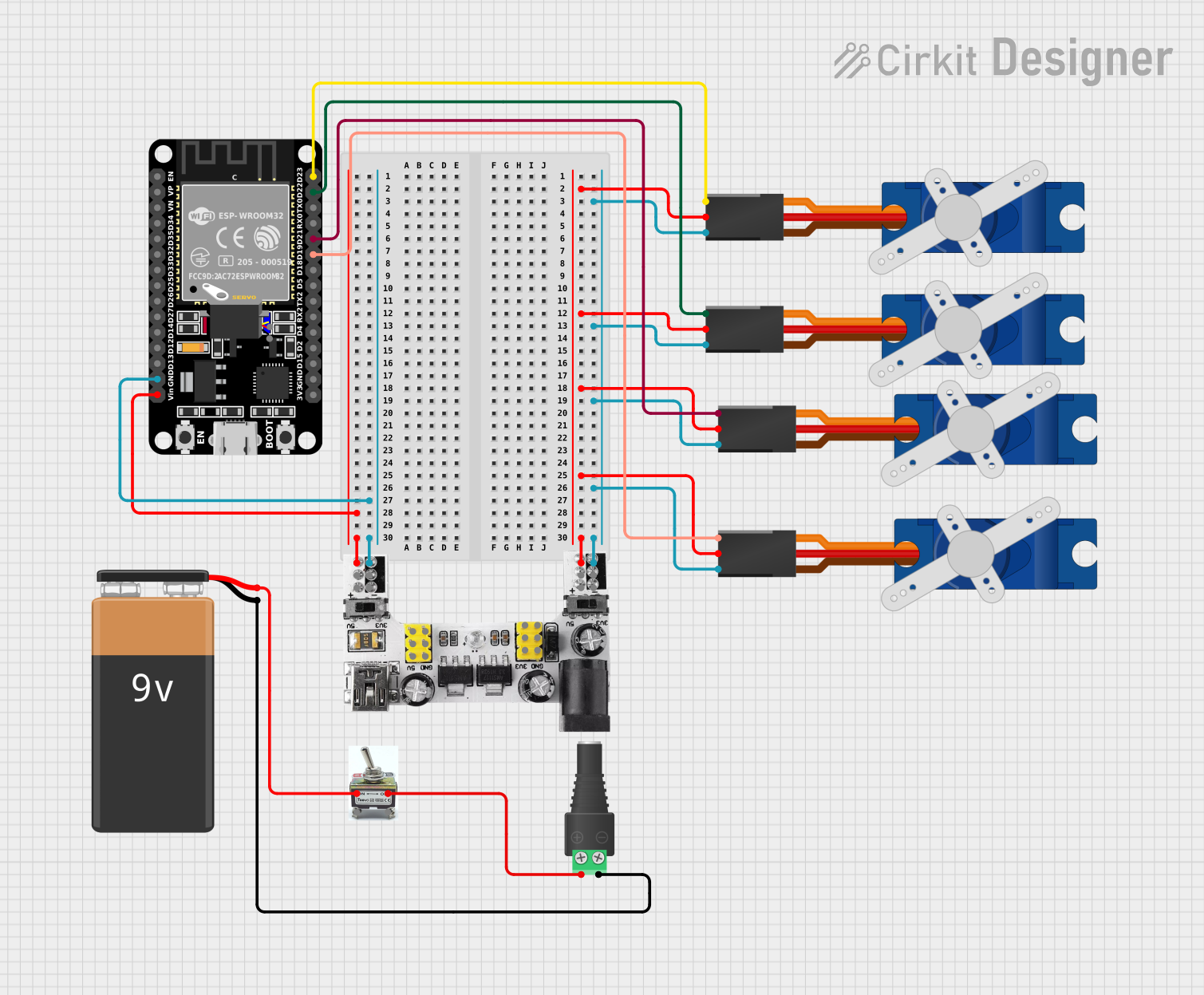
Summary
The circuit in question appears to be designed for controlling multiple servo motors using an ESP32 microcontroller. The ESP32 is powered by a breadboard power module that can supply both 3.3V and 5V, which is in turn powered by a 9V battery through a toggle switch and a barrel jack with a terminal block. The servos are powered by the 5V output from the breadboard power module and are controlled by specific GPIO pins on the ESP32.
Component List
Microcontroller
- ESP32 (30 pin): A microcontroller with Wi-Fi and Bluetooth capabilities, featuring a wide range of GPIO pins for interfacing with various peripherals.
Servos
- Tower Pro SG90 servo: A small and lightweight servo motor suitable for applications where small movements are required.
Power Supply
- Breadboard Power Module (3.3/5V): A module that provides regulated 3.3V and 5V outputs, typically used to power breadboard circuits.
- 2.1mm Barrel Jack with Terminal Block: A connector that allows for easy connection of a power supply to a circuit.
- 9V Battery: A common battery used to provide power to small electronic circuits.
Switch
- Toggle Switch (toogleswitch-04-01): A switch that can be used to control the power supply to the circuit.
Wiring Details
ESP32 (30 pin)
- GND: Connected to the ground (-) rail of the breadboard power module.
- Vin: Connected to the positive (+) rail of the breadboard power module.
- D23: Connected to the signal pin of the first Tower Pro SG90 servo.
- D22: Connected to the signal pin of the second Tower Pro SG90 servo.
- D21: Connected to the signal pin of the third Tower Pro SG90 servo.
- D19: Connected to the signal pin of the fourth Tower Pro SG90 servo.
Tower Pro SG90 Servos
- +5V: All servos are connected to the positive (+) rail of the breadboard power module.
- GND: All servos are connected to the ground (-) rail of the breadboard power module.
- Signal: Each servo's signal pin is connected to a designated GPIO pin on the ESP32.
Breadboard Power Module (3.3/5V)
- + (5V): Connected to the +5V pins of all Tower Pro SG90 servos and the Vin pin of the ESP32.
- - (GND): Connected to the GND pins of all Tower Pro SG90 servos and the GND pin of the ESP32.
Toggle Switch (toogleswitch-04-01)
- Pin 3: Connected to the positive (+) terminal of the 9V battery.
- Pin 4: Connected to the positive (POS) terminal of the barrel jack with terminal block.
2.1mm Barrel Jack with Terminal Block
- POS: Connected to pin 4 of the toggle switch.
- NEG: Connected to the negative (-) terminal of the 9V battery.
9V Battery
- +: Connected to pin 3 of the toggle switch.
- -: Connected to the NEG terminal of the barrel jack with terminal block.
Documented Code
ESP32 Microcontroller Code (sketch.ino)
void setup() {
  // put your setup code here, to run once:

}

void loop() {
  // put your main code here, to run repeatedly:

}
Note: The code provided for the ESP32 microcontroller is a template and does not contain any specific logic to control the servo motors. This will need to be implemented based on the requirements of the application.
Breadboard Power Module Code (sketch.ino)
void setup() {
  // put your setup code here, to run once:

}

void loop() {
  // put your main code here, to run repeatedly:

}
Note: The code provided for the breadboard power module is a template and is not typically required as the module does not have programmable functionality.
Additional documentation files (documentation.txt) are empty and do not contain any further information.