Cirkit Designer
Your all-in-one circuit design IDE
Home /
Project Documentation
Battery-Powered Raspberry Pi Robotic Motor Controller with PWM
Circuit Documentation
Summary
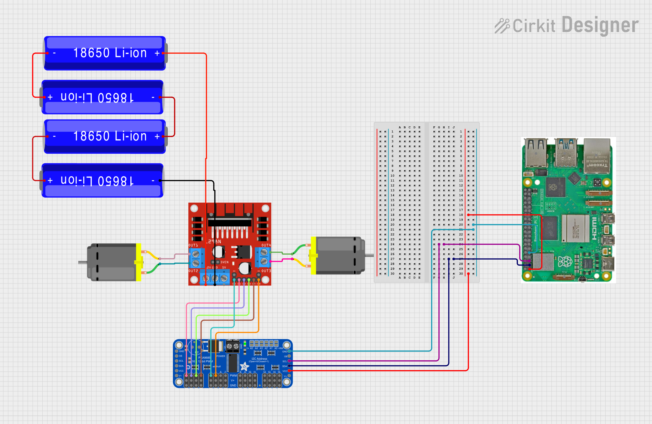
This document provides a detailed overview of a circuit that integrates a Raspberry Pi 5, an Adafruit PCA9685 PWM Servo Breakout, an L298N DC motor driver, multiple DC motors, and several 18650 Li-ion batteries. The circuit is designed to control DC motors using PWM signals from the Raspberry Pi, with power supplied by the Li-ion batteries.
Component List
Raspberry Pi 5
- Description: A powerful single-board computer with multiple GPIO pins for various applications.
- Pins: Type-C, Micro HDMI 1, Micro HDMI 2, Camera 1, Camera 2, PoE, Fan, PCIe, USB 3.0, USB 2.0, Ethernet, 5V, GND, 3.3v, GPIO 14, GPIO 15, GPIO 18, GPIO 23, GPIO 24, GPIO 25, GPIO 8, GPIO 7, GPIO 1, GPIO 12, GPIO 16, GPIO 20, GPIO 21, GPIO 2, GPIO 3, GPIO 4, GPIO 17, GPIO 27, GPIO 22, GPIO 10, GPIO 9, GPIO 11, GPIO 0, GPIO 5, GPIO 6, GPIO 13, GPIO 19, GPIO 26
Adafruit PCA9685 PWM Servo Breakout
- Description: A 16-channel PWM driver that can control servos and LEDs.
- Pins: 5.0V, GND, PWRIN, PWM7, PWM6, PWM5, PWM4, PWM3, PWM2, PWM1, PWM0, VCC, SDA, SCL, OE, PWM15, PWM14, PWM13, PWM12, PWM11, PWM10, PWM9, PWM8
DC Motor
- Description: A simple DC motor with two connection pins.
- Pins: pin 1, pin 2
L298N DC Motor Driver
- Description: A dual H-Bridge motor driver that can control the speed and direction of two DC motors.
- Pins: OUT1, OUT2, 12V, GND, 5V, OUT3, OUT4, 5V-ENA-JMP-I, 5V-ENA-JMP-O, +5V-J1, +5V-J2, ENA, IN1, IN2, IN3, IN4, ENB
18650 Li-ion Battery
- Description: A rechargeable lithium-ion battery.
- Pins: +, -
Wiring Details
Raspberry Pi 5
- GPIO 3 is connected to SCL on the Adafruit PCA9685 PWM Servo Breakout.
- GPIO 2 is connected to SDA on the Adafruit PCA9685 PWM Servo Breakout.
- 3.3v is connected to VCC on the Adafruit PCA9685 PWM Servo Breakout.
- GND is connected to GND on the Adafruit PCA9685 PWM Servo Breakout.
Adafruit PCA9685 PWM Servo Breakout
- SCL is connected to GPIO 3 on the Raspberry Pi 5.
- SDA is connected to GPIO 2 on the Raspberry Pi 5.
- VCC is connected to 3.3v on the Raspberry Pi 5.
- GND is connected to GND on the Raspberry Pi 5.
- PWM5 is connected to ENB on the L298N DC motor driver.
- PWM4 is connected to ENA on the L298N DC motor driver.
- PWM3 is connected to IN4 on the L298N DC motor driver.
- PWM2 is connected to IN3 on the L298N DC motor driver.
- PWM1 is connected to IN2 on the L298N DC motor driver.
- PWM0 is connected to IN1 on the L298N DC motor driver.
L298N DC Motor Driver
- ENB is connected to PWM5 on the Adafruit PCA9685 PWM Servo Breakout.
- ENA is connected to PWM4 on the Adafruit PCA9685 PWM Servo Breakout.
- IN4 is connected to PWM3 on the Adafruit PCA9685 PWM Servo Breakout.
- IN3 is connected to PWM2 on the Adafruit PCA9685 PWM Servo Breakout.
- IN2 is connected to PWM1 on the Adafruit PCA9685 PWM Servo Breakout.
- IN1 is connected to PWM0 on the Adafruit PCA9685 PWM Servo Breakout.
- OUT1 is connected to pin 2 on the first DC Motor.
- OUT2 is connected to pin 1 on the first DC Motor.
- OUT3 is connected to pin 2 on the second DC Motor.
- OUT4 is connected to pin 1 on the second DC Motor.
- 12V is connected to + on the first 18650 Li-ion Battery.
- GND is connected to - on the fourth 18650 Li-ion Battery.
DC Motor (First)
- pin 2 is connected to OUT1 on the L298N DC motor driver.
- pin 1 is connected to OUT2 on the L298N DC motor driver.
DC Motor (Second)
- pin 2 is connected to OUT3 on the L298N DC motor driver.
- pin 1 is connected to OUT4 on the L298N DC motor driver.
18650 Li-ion Battery
- + on the first battery is connected to 12V on the L298N DC motor driver.
- - on the first battery is connected to + on the second battery.
- - on the second battery is connected to + on the third battery.
- - on the third battery is connected to + on the fourth battery.
- - on the fourth battery is connected to GND on the L298N DC motor driver.
Code
No code is provided for this circuit.
This document provides a comprehensive overview of the circuit, including a summary, component list, wiring details, and code documentation. Each section is designed to offer clear and concise information to facilitate understanding and replication of the circuit.