Cirkit Designer
Your all-in-one circuit design IDE
Home /
Project Documentation
ESP32-Controlled LED Blinker Circuit
Circuit Documentation
Summary of the Circuit
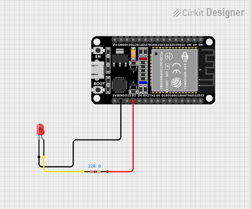
This circuit is designed around the ESP32 microcontroller, which is a versatile and powerful chip with WiFi and Bluetooth capabilities. In this particular application, the ESP32 is used to control an LED. The LED blinks on and off every second, demonstrating the basic digital output functionality of the ESP32. The LED is connected to the ESP32 through a current-limiting resistor to protect the LED from excessive current.
Component List
ESP32 (30 pin)
- Description: A 30-pin microcontroller with WiFi and Bluetooth capabilities.
- Pins: EN, VP, VN, D34, D35, D32, D33, D25, D26, D27, D14, D12, D13, GND, Vin, D23, D22, TX0, RX0, D21, D19, D18, D5, TX2, RX2, D4, D2, D15, 3V3
- Purpose: Acts as the central processing unit of the circuit, controlling the LED blink pattern.
LED: Two Pin (red)
- Description: A basic red LED with two pins: anode and cathode.
- Pins: cathode, anode
- Purpose: Emits light when powered, indicating the output state of the ESP32.
Resistor
- Description: A passive two-pin component that limits the current through the LED.
- Pins: pin1, pin2
- Properties: Resistance: 220 Ohms
- Purpose: Protects the LED from excessive current that could damage it.
Wiring Details
ESP32 (30 pin)
- GND is connected to the cathode of the LED.
- D2 is connected to pin2 of the Resistor.
LED: Two Pin (red)
- Cathode is connected to GND of the ESP32.
- Anode is connected to pin1 of the Resistor.
Resistor
- Pin1 is connected to the anode of the LED.
- Pin2 is connected to D2 of the ESP32.
Documented Code
/* ESP32 LED Blinker
 * This sketch controls an LED connected to GPIO 2 of the ESP32.
 * The LED blinks on and off every second. This circuit demonstrates
 * basic digital output functionality of the ESP32 by using a digital
 * pin to provide a voltage to an LED through a current-limiting resistor.
 */

// Define the LED pin
const int ledPin = 2; // GPIO 2 is often labeled as D2 or IO2 on ESP32 boards

// the setup function runs once when you press reset or power the board
void setup() {
  // initialize digital pin ledPin as an output.
  pinMode(ledPin, OUTPUT);
}

// the loop function runs over and over again forever
void loop() {
  digitalWrite(ledPin, HIGH);   // turn the LED on (HIGH is the voltage level)
  delay(1000);                  // wait for a second
  digitalWrite(ledPin, LOW);    // turn the LED off by making the voltage LOW
  delay(1000);                  // wait for a second
}
- File Name: sketch.ino
- Description: This Arduino sketch is written for the ESP32 microcontroller. It sets up GPIO 2 as an output to control an LED. The
setup()function initializes the pin, and theloop()function toggles the LED state between HIGH and LOW every second, creating a blinking effect.