ESP32-Controlled HX711 Load Cell Weighing System
Circuit Documentation
Summary
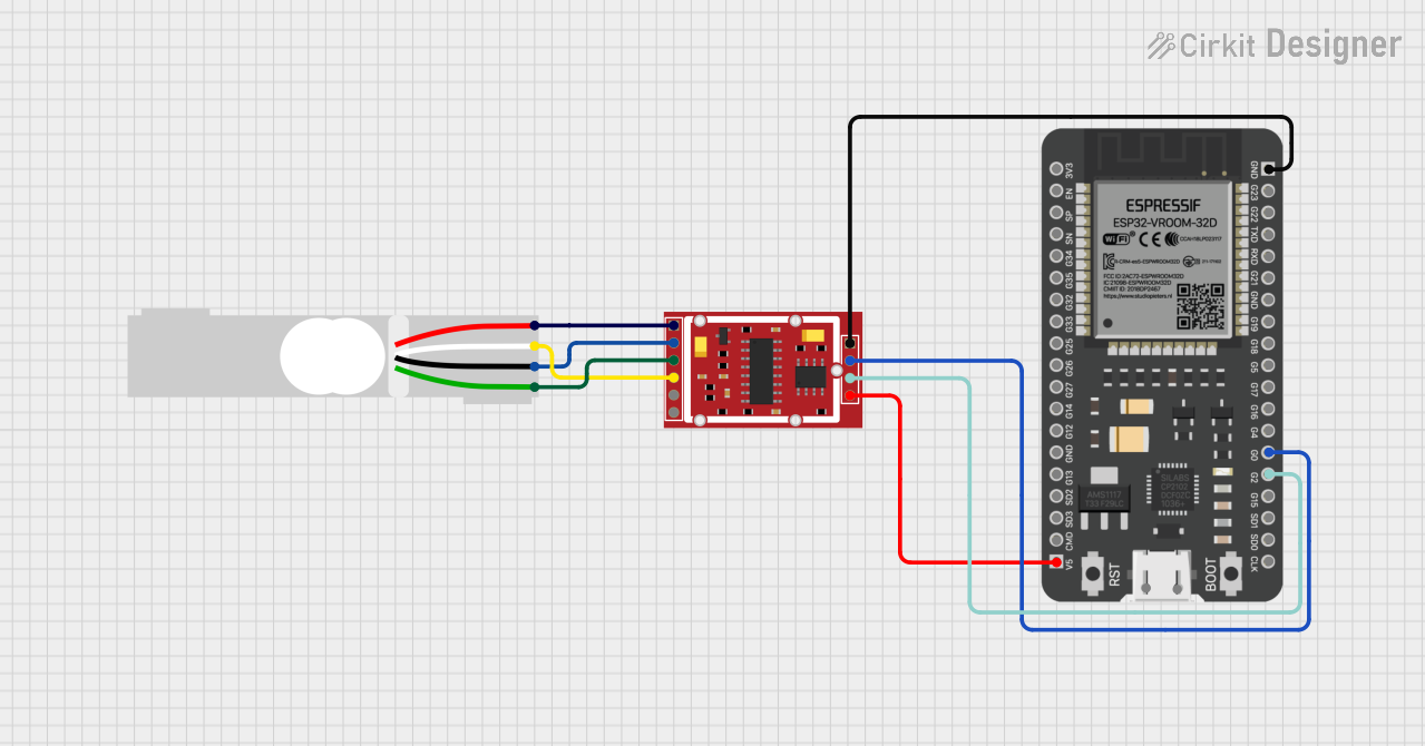
The circuit in question is designed to interface a load cell with an HX711 Weighing Sensor Module for signal amplification and digitization, which then communicates with an ESP32 microcontroller. The load cell is a transducer that converts force into an electrical signal, while the HX711 module amplifies this signal and converts it to a digital form for the ESP32 to process. The ESP32 can then use this data for various applications such as weight measurement or monitoring.
Component List
Load Cell - Red/white/black/green
- Description: A transducer that converts force into an electrical signal.
- Pins: E+, A-, E-, A+
HX711 Weighing Sensor Module
- Description: An amplifier and ADC converter for load cell signals.
- Pins: B-, B+, A-, A+, E-, E+, VCC, CK/TX, DO/RX, GND
ESP32 - 38 pins
- Description: A microcontroller with Wi-Fi and Bluetooth capabilities.
- Pins: 3V3, EN, SP, SN, G34, G35, G32, G33, G25, G26, G27, G14, G12, GND, G13, SD2, SD3, CMD, 5V, G23, G22, TXD, RXD, G21, G19, G18, G5, G17, G16, G4, G0, G2, G15, SD1, SD0, CLK
Wiring Details
Load Cell - Red/white/black/green
- E+: Connected to HX711 E+
- A-: Connected to HX711 A-
- E-: Connected to HX711 E-
- A+: Connected to HX711 A+
HX711 Weighing Sensor Module
- E+: Connected to Load Cell E+
- A-: Connected to Load Cell A-
- E-: Connected to Load Cell E-
- A+: Connected to Load Cell A+
- VCC: Connected to ESP32 5V
- CK/TX: Connected to ESP32 G2
- DO/RX: Connected to ESP32 G0
- GND: Connected to ESP32 GND
ESP32 - 38 pins
- 5V: Connected to HX711 VCC
- G2: Connected to HX711 CK/TX
- G0: Connected to HX711 DO/RX
- GND: Connected to HX711 GND
Code Documentation
No code has been provided for the microcontroller. The ESP32 would typically be programmed to initialize the HX711 module, read the digital output from the HX711, and then process the data accordingly. The code would include setup routines, the main loop for continuous reading, and possibly communication routines if the data is to be sent to another device or displayed.