Cirkit Designer
Your all-in-one circuit design IDE
Home /
Project Documentation
Industrial Power Distribution and Safety Control System

Circuit Documentation
Summary of the Circuit
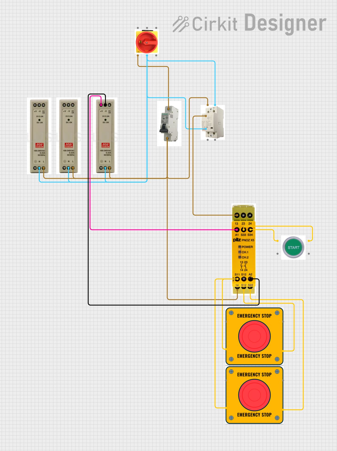
The circuit described by the provided inputs is a power distribution and safety control system. It includes a main isolator to disconnect the power supply, multiple power supply units (PSUs) to provide different voltage levels (5V, 12V, and 24V), a main contactor to control the connection to the load, a miniature circuit breaker (MCB) for overcurrent protection, a safety relay for emergency stop (E-Stop) functionality, and start and E-Stop switches for user interaction.
Component List
MAIN CONTACTOR
- Description: A device used to switch the main power supply to the load.
- Pins: 1, 3, 2, 4, A1, A2
5V PSU
- Description: A power supply unit that provides a 5V output.
- Pins: 5V+, GND, 5V OK, PE, N, L
12V PSU
- Description: A power supply unit that provides a 12V output.
- Pins: 12V+, GND, 12V OK, PE, N, L
24V PSU
- Description: A power supply unit that provides a 24V output.
- Pins: 24V+, GND, 24V OK, PE, N, L
MAIN ISOLATOR (3P)
- Description: A three-pole isolator used to disconnect the power supply for maintenance or emergency purposes.
- Pins: L (SUPPLY), N (SUPPLY), PE (SUPPLY), L (OUT), N (OUT), PE (OUT)
MCB
- Description: A miniature circuit breaker that provides overcurrent protection.
- Pins: IN, OUT
Safety Relay
- Description: A relay used to implement safety functions, such as emergency stopping and safety guarding.
- Pins: 13, 23, 24, A1, S33, S34, S11, S12, A2, 14, S22
E Stop
- Description: An emergency stop switch that allows a user to stop the machine in case of an emergency.
- Pins: NO 1, NO 2, NC 1, NC 2
START SWITCH
- Description: A switch used to start the machine or process.
- Pins: NO 1, NC 1, NO 2, NC 2
Wiring Details
MAIN CONTACTOR
- Wiring:
- A1 connected to Safety Relay pin 13
- A2 connected to Neutral (N) net
- 1 connected to Line (L) net
5V PSU
- Wiring:
- 5V+ (Not connected in the provided net list)
- GND (Not connected in the provided net list)
- 5V OK (Not connected in the provided net list)
- PE (Not connected in the provided net list)
- N connected to Neutral (N) net
- L connected to Line (L) net
12V PSU
- Wiring:
- 12V+ (Not connected in the provided net list)
- GND (Not connected in the provided net list)
- 12V OK (Not connected in the provided net list)
- PE (Not connected in the provided net list)
- N connected to Neutral (N) net
- L connected to Line (L) net
24V PSU
- Wiring:
- 24V+ connected to Safety Relay pin A1
- GND connected to Safety Relay pin A2
- 24V OK (Not connected in the provided net list)
- PE (Not connected in the provided net list)
- N connected to Neutral (N) net
- L connected to Line (L) net
MAIN ISOLATOR (3P)
- Wiring:
- L (OUT) connected to MCB pin OUT
- N (OUT) connected to Neutral (N) net
- PE (OUT) (Not connected in the provided net list)
- L (SUPPLY), N (SUPPLY), PE (SUPPLY) (Not connected in the provided net list)
MCB
- Wiring:
- IN connected to Line (L) net
- OUT connected to Main Isolator (3P) pin L (OUT)
Safety Relay
- Wiring:
- 13 connected to MAIN CONTACTOR pin A1
- 14 connected to Line (L) net
- A1 connected to 24V PSU pin 24V+
- A2 connected to 24V PSU pin GND
- S11 connected to E Stop pin NC 1
- S12 connected to E Stop pin NC 2
- S22 connected to E Stop pin NC 2
- S33 connected to START SWITCH pin NO 2
- S34 connected to START SWITCH pin NO 1
E Stop (Instance 1)
- Wiring:
- NC 1 connected to Safety Relay pin S11
- NC 2 connected to Safety Relay pin S22
E Stop (Instance 2)
- Wiring:
- NC 1 connected to E Stop (Instance 1) pin NC 1
- NC 2 connected to Safety Relay pin S12
START SWITCH
- Wiring:
- NO 1 connected to Safety Relay pin S34
- NO 2 connected to Safety Relay pin S33
Documented Code
There is no code provided for any microcontrollers in the circuit. If code becomes available, it should be documented here with appropriate comments and explanations for each function and routine.