Cirkit Designer
Your all-in-one circuit design IDE
Home /
Project Documentation
Arduino UNO Based IR Sensor Alarm System
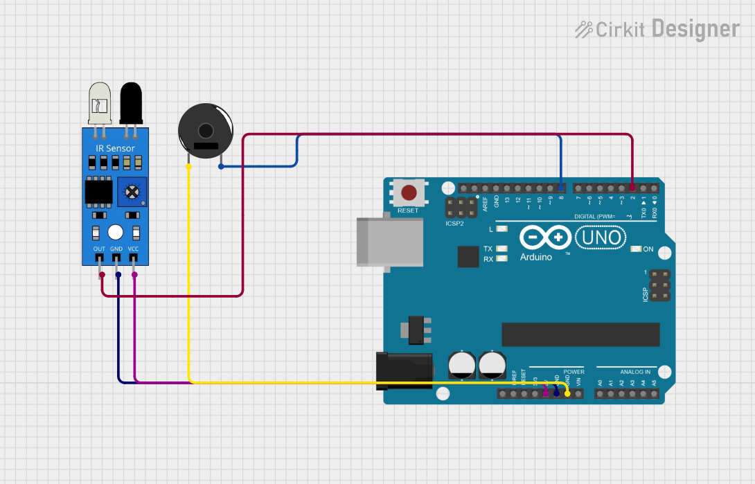
Circuit Documentation
Summary of the Circuit
This circuit is designed to detect an event (such as the presence of an object) using an infrared (IR) sensor and provide an audible alert through a Piezo Buzzer. The Arduino UNO serves as the central processing unit, reading the output from the IR sensor and controlling the state of the Piezo Buzzer accordingly. When the IR sensor detects the specified event, the Arduino activates the buzzer.
Component List
Arduino UNO
- Description: A microcontroller board based on the ATmega328P.
- Purpose: Acts as the central controller for the circuit, reading sensor data and driving the buzzer.
- Pins: UNUSED, IOREF, Reset, 3.3V, 5V, GND, Vin, A0-A5, SCL, SDA, AREF, D0-D13.
IR Sensor
- Description: An infrared sensor capable of detecting infrared light.
- Purpose: Senses the presence of an object or event and sends a signal to the Arduino.
- Pins: out, gnd, vcc.
Piezo Buzzer
- Description: An electronic device that emits a tone when voltage is applied.
- Purpose: Provides an audible alert when activated by the Arduino.
- Pins: pin 1, pin 2.
Wiring Details
Arduino UNO
- 5V pin is connected to the VCC pin of the IR sensor.
- GND pin is connected to the GND pin of the IR sensor and pin 1 of the Piezo Buzzer.
- D2 pin is connected to the OUT pin of the IR sensor.
- D8 pin is connected to pin 2 of the Piezo Buzzer.
IR Sensor
- VCC pin is connected to the 5V pin of the Arduino UNO.
- GND pin is connected to the GND pin of the Arduino UNO.
- OUT pin is connected to the D2 pin of the Arduino UNO.
Piezo Buzzer
- Pin 1 is connected to the GND pin of the Arduino UNO.
- Pin 2 is connected to the D8 pin of the Arduino UNO.
Documented Code
// Code for Arduino UNO
int sensorPin = 2; // IR sensor OUT pin connected to Digital Pin 2
int buzzerPin = 8; // Piezo Buzzer pin connected to Digital Pin 8
int sensorValue = 0; // Variable to store the sensor output

void setup() {
  pinMode(sensorPin, INPUT); // Set the sensor pin as input
  pinMode(buzzerPin, OUTPUT); // Set the buzzer pin as output
}

void loop() {
  sensorValue = digitalRead(sensorPin); // Read the sensor output
  if (sensorValue == HIGH) {
    // If the sensor detects the specified event (assuming HIGH means event detected)
    digitalWrite(buzzerPin, HIGH); // Turn on the buzzer
  } else {
    digitalWrite(buzzerPin, LOW); // Turn off the buzzer
  }
}
Filename: sketch.ino
This code is written for the Arduino UNO microcontroller. It initializes the sensor and buzzer pins, reads the sensor output in the main loop, and turns the buzzer on or off based on the sensor reading. The assumption here is that a HIGH signal from the IR sensor indicates the detection of the specified event.