Arduino UNO-Based Smart Distance Sensor with LCD Display and Servo Control
Circuit Documentation
Summary
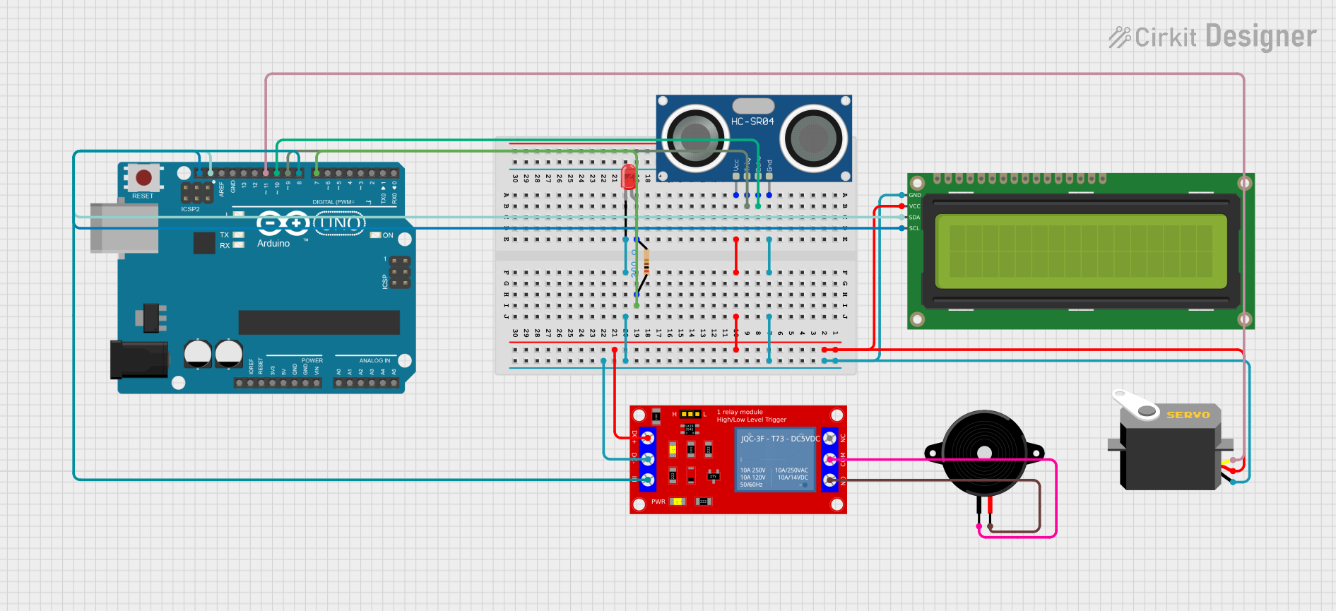
This circuit is designed to measure distance using an HC-SR04 Ultrasonic Sensor and display the measured distance on a 16x2 I2C LCD. Additionally, the circuit controls a servo motor, a relay module, an LED, and a piezo speaker based on the measured distance. The Arduino UNO microcontroller is used to manage all the components and execute the embedded code.
Component List
Arduino UNO
- Description: Microcontroller board based on the ATmega328P.
- Pins: UNUSED, IOREF, Reset, 3.3V, 5V, GND, Vin, A0, A1, A2, A3, A4, A5, SCL, SDA, AREF, D13, D12, D11, D10, D9, D8, D7, D6, D5, D4, D3, D2, D1, D0
1 Channel 5V Relay Module
- Description: Relay module for controlling high voltage devices.
- Pins: VCC+, VCC- (GND), IN, N.O., COM, N.C.
16x2 I2C LCD
- Description: LCD display with I2C interface.
- Pins: GND, VCC, SDA, SCL
Servo
- Description: Servo motor for precise control of angular position.
- Pins: gnd, vcc, pulse
LED: Two Pin (red)
- Description: Red LED for visual indication.
- Pins: cathode, anode
HC-SR04 Ultrasonic Sensor
- Description: Ultrasonic sensor for distance measurement.
- Pins: VCC, TRIG, ECHO, GND
Resistor
- Description: 200 Ohms resistor.
- Pins: pin1, pin2
Piezo Speaker
- Description: Piezoelectric speaker for sound output.
- Pins: pin1, pin2
Wiring Details
Arduino UNO
- D10: Connected to HC-SR04 Ultrasonic Sensor (ECHO)
- D9: Connected to HC-SR04 Ultrasonic Sensor (TRIG)
- D7: Connected to Resistor (pin1)
- SCL: Connected to 16x2 I2C LCD (SCL)
- SDA: Connected to 16x2 I2C LCD (SDA)
- D11: Connected to Servo (pulse)
- D8: Connected to 1 Channel 5V Relay Module (IN)
1 Channel 5V Relay Module
- VCC+: Connected to 5V power rail
- VCC- (GND): Connected to GND rail
- IN: Connected to Arduino UNO (D8)
- N.O.: Connected to Piezo Speaker (pin2)
- COM: Connected to Piezo Speaker (pin1)
16x2 I2C LCD
- GND: Connected to GND rail
- VCC: Connected to 5V power rail
- SDA: Connected to Arduino UNO (SDA)
- SCL: Connected to Arduino UNO (SCL)
Servo
- gnd: Connected to GND rail
- vcc: Connected to 5V power rail
- pulse: Connected to Arduino UNO (D11)
LED: Two Pin (red)
- cathode: Connected to GND rail
- anode: Connected to Resistor (pin2)
HC-SR04 Ultrasonic Sensor
- VCC: Connected to 5V power rail
- TRIG: Connected to Arduino UNO (D9)
- ECHO: Connected to Arduino UNO (D10)
- GND: Connected to GND rail
Resistor
- pin1: Connected to Arduino UNO (D7)
- pin2: Connected to LED (anode)
Piezo Speaker
- pin1: Connected to 1 Channel 5V Relay Module (COM)
- pin2: Connected to 1 Channel 5V Relay Module (N.O.)
Code Documentation
#include <Wire.h>
#include <LiquidCrystal_I2C.h>
#include <Servo.h>

// Initialize the LCD (I2C address, width, height)
LiquidCrystal_I2C lcd(0x27, 16, 2); // Change I2C address if needed
Servo myServo;                      // Create a servo object

const int trigPin = 9;             // Pin for the Trig
const int echoPin = 10;             // Pin for the Echo
const int servoPin = 11;            // Pin for the Servo
const int relayPin = 8;             // Pin for the Relay
const int ledPin = 7;               // Pin for the LED

void setup() {
  lcd.begin();                     // Initialize the LCD
  lcd.backlight();                 // Turn on the LCD backlight
  lcd.clear();                     // Clear any previous content

  pinMode(trigPin, OUTPUT);       // Set Trig pin as output
  pinMode(echoPin, INPUT);        // Set Echo pin as input
  pinMode(relayPin, OUTPUT);      // Set Relay pin as output
  pinMode(ledPin, OUTPUT);        // Set LED pin as output
  myServo.attach(servoPin);        // Attach the servo to the pin
  Serial.begin(9600);              // Start serial communication for debugging
}

void loop() {
  // Clear the Trig pin
  digitalWrite(trigPin, LOW);
  delayMicroseconds(2);
  // Set the Trig pin HIGH for 10 microseconds
  digitalWrite(trigPin, HIGH);
  delayMicroseconds(10);
  digitalWrite(trigPin, LOW);

  // Read the Echo pin
  long duration = pulseIn(echoPin, HIGH);
  // Calculate the distance in cm
  float distance = duration * 0.034 / 2;

  // Display the distance on the LCD
  lcd.setCursor(0, 0);           // Set cursor to first row
  lcd.print("Distance: ");
  lcd.print(distance);            // Print distance
  lcd.print(" cm");

  // Move the servo and control relay and LED based on distance
  if (distance < 10) {           // If distance is less than 10 cm
    myServo.write(180);          // Move servo to 180 degrees
    digitalWrite(relayPin, HIGH); // Turn on relay
    digitalWrite(ledPin, HIGH);   // Turn on LED
  } else {
    myServo.write(0);            // Move servo to 0 degrees
    digitalWrite(relayPin, LOW);  // Turn off relay
    digitalWrite(ledPin, LOW);    // Turn off LED
  }

  Serial.print("Distance: ");
  Serial.print(distance);
  Serial.println(" cm");         // Print distance to Serial Monitor

  delay(500); // Wait for a bit before the next reading
}
This code initializes the LCD, servo, and pins for the ultrasonic sensor, relay, and LED. In the loop function, it measures the distance using the ultrasonic sensor, displays the distance on the LCD, and controls the servo, relay, and LED based on the measured distance. The distance is also printed to the Serial Monitor for debugging purposes.