
Arduino UNO Controlled DC Motor with Potentiometer Speed Adjustment
View and Edit Project In Cirkit Designer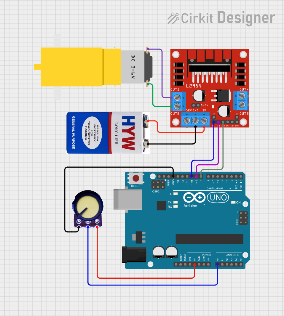
Circuit Documentation
Summary
This circuit is designed to control a DC motor using an Arduino UNO, a potentiometer, and an L298N DC motor driver. The potentiometer is used to adjust the speed of the motor, which is read by the Arduino and then used to control the motor driver. The motor driver, in turn, powers the DC motor based on the signals received from the Arduino.
Component List
Arduino UNO
- Description: A microcontroller board based on the ATmega328P.
- Pins: UNUSED, IOREF, Reset, 3.3V, 5V, GND, Vin, A0, A1, A2, A3, A4, A5, SCL, SDA, AREF, D13, D12, D11, D10, D9, D8, D7, D6, D5, D4, D3, D2, D1, D0
L298N DC motor driver
- Description: A dual H-Bridge motor driver module that allows control of the speed and direction of two DC motors.
- Pins: OUT1, OUT2, 12V, GND, 5V, OUT3, OUT4, 5V-ENA-JMP-I, 5V-ENA-JMP-O, +5V-J1, +5V-J2, ENA, IN1, IN2, IN3, IN4, ENB
Motor amarillo motorreductor hobby
- Description: A small DC motor with a gearbox for hobby projects.
- Pins: vcc, GND
Potentiometer
- Description: A variable resistor used to adjust voltage levels.
- Pins: GND, Output, VCC
9V battery
- Description: A standard 9V battery used to power the motor driver.
- Pins: +, -
Wiring Details
Arduino UNO
- 5V connected to VCC of the Potentiometer
- A0 connected to Output of the Potentiometer
- GND connected to GND of the Potentiometer
- D10 connected to ENA of the L298N DC motor driver
- D9 connected to IN1 of the L298N DC motor driver
- D8 connected to IN2 of the L298N DC motor driver
L298N DC motor driver
- OUT1 connected to GND of the Motor amarillo motorreductor hobby
- OUT2 connected to vcc of the Motor amarillo motorreductor hobby
- GND connected to - of the 9V battery
- 5V connected to + of the 9V battery
Motor amarillo motorreductor hobby
- GND connected to OUT1 of the L298N DC motor driver
- vcc connected to OUT2 of the L298N DC motor driver
Potentiometer
- VCC connected to 5V of the Arduino UNO
- Output connected to A0 of the Arduino UNO
- GND connected to GND of the Arduino UNO
9V battery
- - connected to GND of the L298N DC motor driver
- + connected to 5V of the L298N DC motor driver
Documented Code
Arduino UNO Code
// Declaring where our module is wired
int in1 = 8;
int in2 = 9;
int ConA = 10; // Don't forget this is a PWM DI/DO
int speed1;

void setup() {
  pinMode(8, OUTPUT);
  pinMode(9, OUTPUT);
  pinMode(10, OUTPUT);
}

void loop() {
  digitalWrite(in1, LOW);  // Switch between this HIGH and LOW to change direction
  digitalWrite(in2, HIGH);
  speed1 = analogRead(A0);  // We read the analog value from the potentiometer
  speed1 = speed1 * 0.2492668622;  // Calibrate it
  analogWrite(ConA, speed1);  // Then inject it to our motor
}
This code initializes the pins connected to the motor driver as outputs and reads the analog value from the potentiometer to control the speed of the motor. The direction of the motor can be changed by toggling the digitalWrite values for in1 and in2.