Arduino UNO Bluetooth Controlled Drone with GPS and Camera
Circuit Documentation
Summary
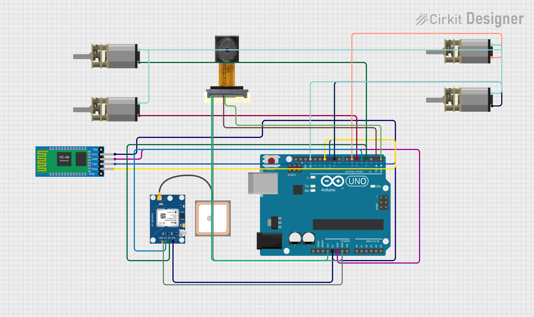
This document provides a detailed overview of a circuit designed to control a drone using an Arduino UNO microcontroller. The drone is equipped with a Bluetooth module for communication, a GPS module for location tracking, a camera module for capturing images, and four DC Mini Metal Gear Motors for propulsion. The Arduino UNO is programmed to handle Bluetooth commands, read GPS and camera data, and control the motors accordingly.
Component List
Arduino UNO
- Description: A microcontroller board based on the ATmega328P.
- Pins: UNUSED, IOREF, Reset, 3.3V, 5V, GND, Vin, A0, A1, A2, A3, A4, A5, SCL, SDA, AREF, D13, D12, D11, D10, D9, D8, D7, D6, D5, D4, D3, D2, D1, D0
DC Mini Metal Gear Motor
- Description: A small DC motor with metal gears for increased torque.
- Pins: IN1, IN2
Bluetooth HC-06
- Description: A Bluetooth module for wireless communication.
- Pins: VCC, GND, TXD, RXD
OV2640 Camera Module
- Description: A camera module for capturing images.
- Pins: 3.3V, GND, SIOC, SIOD, VSync, HRef, PCLK, XCLK, D9, D8, D7, D6, D5, D4, D3, D2, RET, PWDN
GPS NEO 6M
- Description: A GPS module for location tracking.
- Pins: VCC, RX, TX, GND
Wiring Details
Arduino UNO
- 3.3V: Connected to 3.3V pin of OV2640 Camera Module.
- 5V: Connected to VCC pins of GPS NEO 6M and Bluetooth HC-06.
- GND: Connected to GND pins of Bluetooth HC-06, GPS NEO 6M, OV2640 Camera Module, and IN2 pins of all DC Mini Metal Gear Motors.
- D0: Connected to D7 pin of OV2640 Camera Module.
- D1: Connected to D8 pin of OV2640 Camera Module.
- D3: Connected to RX pin of GPS NEO 6M and IN1 pin of one DC Mini Metal Gear Motor.
- D4: Connected to TX pin of GPS NEO 6M.
- D5: Connected to IN1 pin of one DC Mini Metal Gear Motor.
- D6: Connected to IN1 pin of one DC Mini Metal Gear Motor.
- D9: Connected to IN1 pin of one DC Mini Metal Gear Motor.
- D10: Connected to TXD pin of Bluetooth HC-06.
- D11: Connected to RXD pin of Bluetooth HC-06.
DC Mini Metal Gear Motor
- IN1: Connected to D3, D5, D6, and D9 pins of Arduino UNO.
- IN2: Connected to GND pin of Arduino UNO.
Bluetooth HC-06
- VCC: Connected to 5V pin of Arduino UNO.
- GND: Connected to GND pin of Arduino UNO.
- TXD: Connected to D10 pin of Arduino UNO.
- RXD: Connected to D11 pin of Arduino UNO.
OV2640 Camera Module
- 3.3V: Connected to 3.3V pin of Arduino UNO.
- GND: Connected to GND pin of Arduino UNO.
- D7: Connected to D0 pin of Arduino UNO.
- D8: Connected to D1 pin of Arduino UNO.
GPS NEO 6M
- VCC: Connected to 5V pin of Arduino UNO.
- GND: Connected to GND pin of Arduino UNO.
- TX: Connected to D4 pin of Arduino UNO.
- RX: Connected to D3 pin of Arduino UNO.
Code Documentation
/*
 * Arduino Bluetooth Controlled Drone with GPS and Camera
 * This code sets up Bluetooth communication, reads GPS and camera data,
 * and controls the drone's motors using commands sent from an HTML interface.
 */

#include <SoftwareSerial.h>

// Define pins for Bluetooth module
#define BT_RX 10
#define BT_TX 11

// Define pins for motor control
#define MOTOR1_PIN 3
#define MOTOR2_PIN 5
#define MOTOR3_PIN 6
#define MOTOR4_PIN 9

// Define pins for GPS module
#define GPS_RX 4
#define GPS_TX 3

// Define pins for Camera module
#define CAMERA_RX 7
#define CAMERA_TX 8

SoftwareSerial bluetooth(BT_RX, BT_TX); // RX, TX
SoftwareSerial gps(GPS_RX, GPS_TX); // RX, TX
SoftwareSerial camera(CAMERA_RX, CAMERA_TX); // RX, TX

void setup() {
  // Initialize serial communication with Bluetooth module
  bluetooth.begin(9600);
  Serial.begin(9600);

  // Initialize GPS module
  gps.begin(9600);

  // Initialize Camera module
  camera.begin(9600);

  // Initialize motor control pins as outputs
  pinMode(MOTOR1_PIN, OUTPUT);
  pinMode(MOTOR2_PIN, OUTPUT);
  pinMode(MOTOR3_PIN, OUTPUT);
  pinMode(MOTOR4_PIN, OUTPUT);
}

void loop() {
  // Check if data is available from Bluetooth module
  if (bluetooth.available()) {
    char command = bluetooth.read();
    Serial.println(command);

    // Control motors based on received command
    switch (command) {
      case '1':
        digitalWrite(MOTOR1_PIN, HIGH);
        break;
      case '2':
        digitalWrite(MOTOR2_PIN, HIGH);
        break;
      case '3':
        digitalWrite(MOTOR3_PIN, HIGH);
        break;
      case '4':
        digitalWrite(MOTOR4_PIN, HIGH);
        break;
      case '0':
        digitalWrite(MOTOR1_PIN, LOW);
        digitalWrite(MOTOR2_PIN, LOW);
        digitalWrite(MOTOR3_PIN, LOW);
        digitalWrite(MOTOR4_PIN, LOW);
        break;
      default:
        // Do nothing for unrecognized commands
        break;
    }
  }

  // Check if data is available from GPS module
  if (gps.available()) {
    String gpsData = gps.readStringUntil('\n');
    Serial.println("GPS Data: " + gpsData);
  }

  // Check if data is available from Camera module
  if (camera.available()) {
    String cameraData = camera.readStringUntil('\n');
    Serial.println("Camera Data: " + cameraData);
  }
}
This code initializes the Bluetooth, GPS, and Camera modules and sets up the motor control pins. It continuously checks for data from the Bluetooth module to control the motors and reads data from the GPS and Camera modules, printing the data to the serial monitor.