
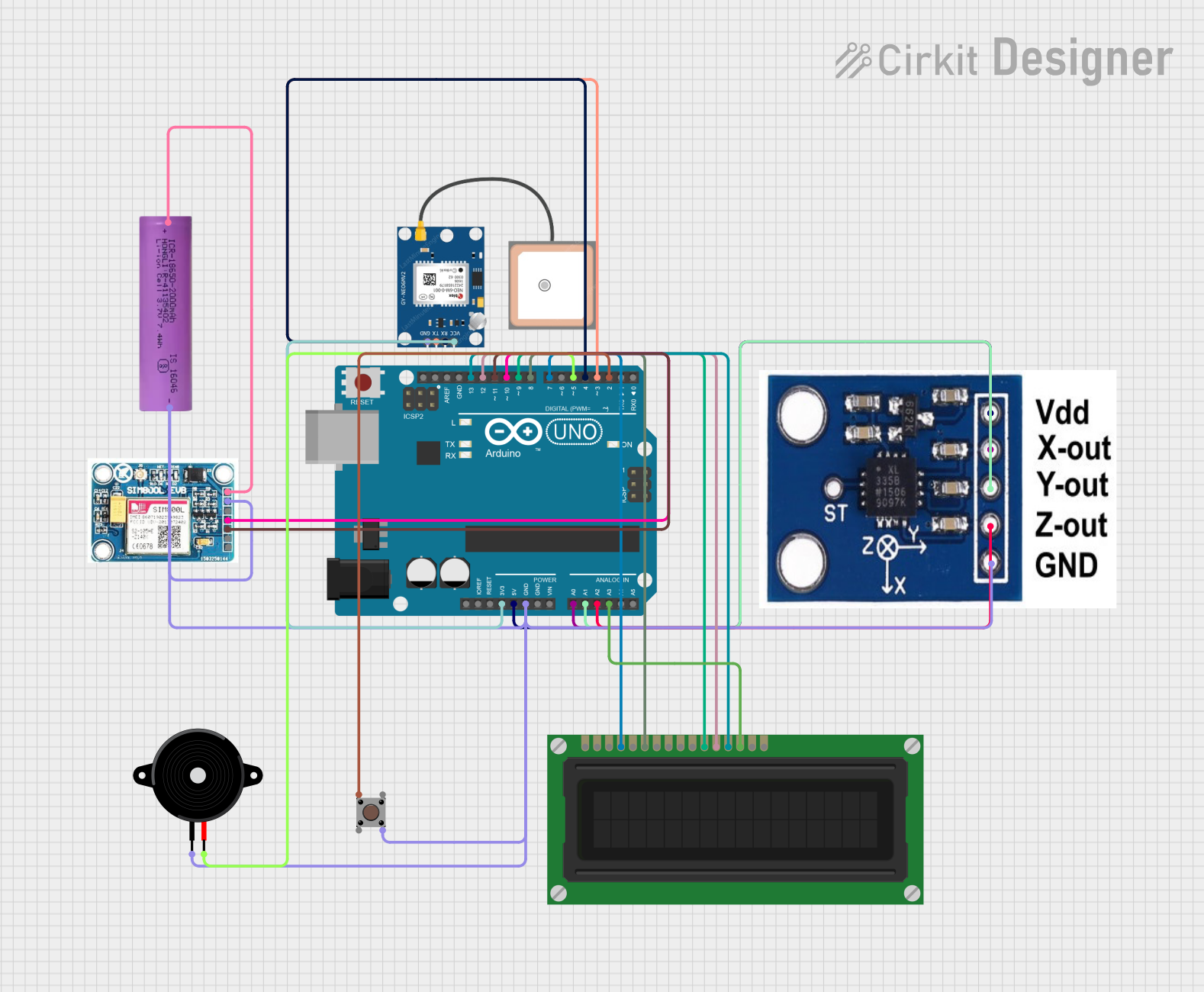
Accident Detection System Documentation
Summary
This document provides a detailed overview of an Accident Detection System designed using an Arduino UNO microcontroller. The system detects changes in speed and collisions using an accelerometer. Upon detecting a collision, a buzzer sounds for 20 seconds, the GPS module senses the location and displays the coordinates on an LCD, and the GSM module calls and sends a message to an emergency number.
Component List
Arduino UNO
- Description: Microcontroller board based on the ATmega328P.
- Pins: UNUSED, IOREF, Reset, 3.3V, 5V, GND, Vin, A0, A1, A2, A3, A4, A5, SCL, SDA, AREF, D13, D12, D11, D10, D9, D8, D7, D6, D5, D4, D3, D2, D1, D0
ADXXL335
- Description: 3-axis accelerometer.
- Pins: VCC, X-OUT, Y-OUT, Z-OUT, GND
GPS NEO 6M
- Description: GPS module for location tracking.
- Pins: VCC, RX, TX, GND
LCD Display (16 pin)
- Description: 16x2 character LCD display.
- Pins: VSS, VDD, VO, RS, R_W, E, DB0, DB1, DB2, DB3, DB4, DB5, DB6, DB7, A, K
Pushbutton
- Description: Simple pushbutton switch.
- Pins: Pin 3 (out), Pin 4 (out), Pin 1 (in), Pin 2 (in)
Piezo Speaker
- Description: Small piezoelectric speaker.
- Pins: pin1, pin2
SIM 800L V2.0 GSM
- Description: GSM module for communication.
- Pins: SIM_TXD, VDD, SIM.RXD, 5V/4V, GND, RST
Li-ion battery 18650-2000mAh 3.7V 7.4WH
- Description: Rechargeable lithium-ion battery.
- Pins: +, -
Wiring Details
Arduino UNO
- 3.3V to GPS NEO 6M VCC
- 5V to ADXXL335 VCC
- GND to SIM 800L V2.0 GSM GND, Li-ion battery 18650-2000mAh 3.7V 7.4WH -, Pushbutton Pin 4 (out), ADXXL335 GND, Piezo Speaker pin1, GPS NEO 6M GND
- A0 to ADXXL335 X-OUT
- A1 to ADXXL335 Y-OUT
- A2 to ADXXL335 Z-OUT
- A3 to LCD Display (16 pin) DB7
- D13 to LCD Display (16 pin) DB6
- D12 to LCD Display (16 pin) DB5
- D11 to SIM 800L V2.0 GSM SIM.RXD
- D10 to SIM 800L V2.0 GSM SIM_TXD
- D9 to LCD Display (16 pin) DB4
- D8 to LCD Display (16 pin) E
- D7 to LCD Display (16 pin) RS
- D5 to Piezo Speaker pin2
- D4 to GPS NEO 6M RX
- D3 to GPS NEO 6M TX
- D2 to Pushbutton Pin 1 (in)
ADXXL335
- VCC to Arduino UNO 5V
- X-OUT to Arduino UNO A0
- Y-OUT to Arduino UNO A1
- Z-OUT to Arduino UNO A2
- GND to Arduino UNO GND
GPS NEO 6M
- VCC to Arduino UNO 3.3V
- RX to Arduino UNO D4
- TX to Arduino UNO D3
- GND to Arduino UNO GND
LCD Display (16 pin)
- DB7 to Arduino UNO A3
- DB6 to Arduino UNO D13
- DB5 to Arduino UNO D12
- DB4 to Arduino UNO D9
- E to Arduino UNO D8
- RS to Arduino UNO D7
Pushbutton
- Pin 1 (in) to Arduino UNO D2
- Pin 4 (out) to Arduino UNO GND
Piezo Speaker
- pin1 to Arduino UNO GND
- pin2 to Arduino UNO D5
SIM 800L V2.0 GSM
- SIM.RXD to Arduino UNO D11
- SIM_TXD to Arduino UNO D10
- GND to Arduino UNO GND
- 5V/4V to Li-ion battery 18650-2000mAh 3.7V 7.4WH +
Li-ion battery 18650-2000mAh 3.7V 7.4WH
- + to SIM 800L V2.0 GSM 5V/4V
- - to Arduino UNO GND
Code Documentation
/*
 * Accident Detection System
 * This system detects changes in speed and collisions using an accelerometer.
 * If a collision is detected, a buzzer sounds for 20 seconds. The GPS module
 * senses the location and displays the coordinates on an LCD. The GSM module
 * calls and sends a message to an emergency number.
 */

#include <Wire.h>
#include <LiquidCrystal.h>
#include <SoftwareSerial.h>

// Pin definitions
const int buzzerPin = 5;
const int buttonPin = 2;
const int gpsRxPin = 3;
const int gpsTxPin = 4;
const int gsmTxPin = 10;
const int gsmRxPin = 11;

// Accelerometer pins
const int xPin = A0;
const int yPin = A1;
const int zPin = A2;

// LCD pins
LiquidCrystal lcd(7, 8, 9, 12, 13, A3);

// Software serial for GPS and GSM
SoftwareSerial gpsSerial(gpsRxPin, gpsTxPin);
SoftwareSerial gsmSerial(gsmTxPin, gsmRxPin);

// Emergency number
const char emergencyNumber[] = "+1234567890";

void setup() {
  pinMode(buzzerPin, OUTPUT);
  pinMode(buttonPin, INPUT);
  lcd.begin(16, 2);
  gpsSerial.begin(9600);
  gsmSerial.begin(9600);
  Serial.begin(9600);
}

void loop() {
  int x = analogRead(xPin);
  int y = analogRead(yPin);
  int z = analogRead(zPin);

  if (detectCollision(x, y, z)) {
    soundBuzzer();
    String location = getGPSLocation();
    displayLocation(location);
    sendEmergencyAlert(location);
  }
}

bool detectCollision(int x, int y, int z) {
  // Simple collision detection logic
  return (x > 600 || y > 600 || z > 600);
}

void soundBuzzer() {
  digitalWrite(buzzerPin, HIGH);
  delay(20000); // 20 seconds delay
  digitalWrite(buzzerPin, LOW);
}

String getGPSLocation() {
  String location = "";
  while (gpsSerial.available()) {
    char c = gpsSerial.read();
    location += c;
  }
  return location;
}

void displayLocation(String location) {
  lcd.clear();
  lcd.print("Location:");
  lcd.setCursor(0, 1);
  lcd.print(location);
}

void sendEmergencyAlert(String location) {
  gsmSerial.print("ATD");
  gsmSerial.print(emergencyNumber);
  gsmSerial.println(";");
  delay(10000); // Wait for call to connect
  gsmSerial.println("ATH"); // Hang up
  gsmSerial.print("AT+CMGF=1\r");
  delay(100);
  gsmSerial.print("AT+CMGS=\"");
  gsmSerial.print(emergencyNumber);
  gsmSerial.println("\"");
  delay(100);
  gsmSerial.print("Accident detected at: ");
  gsmSerial.print(location);
  gsmSerial.write(26); // Ctrl+Z to send SMS
}
This code initializes the necessary components and continuously monitors the accelerometer readings. If a collision is detected, it triggers the buzzer, retrieves the GPS location, displays it on the LCD, and sends an emergency alert via the GSM module.