Arduino Nano Based GPS Tracker with GSM Module and Panic Buttons
Circuit Documentation
Summary
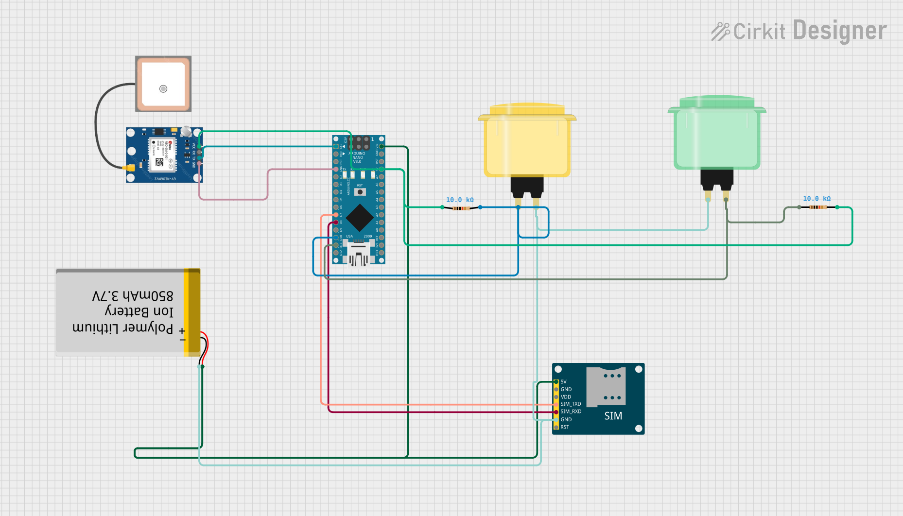
This circuit integrates an Arduino Nano with a GPS module (NEO 6M), a GSM module (SIM800L), two arcade buttons (yellow and green), and a polymer lithium-ion battery. The Arduino Nano serves as the central processing unit, interfacing with the GPS module to obtain location data and with the GSM module to send SMS messages and make calls. The arcade buttons are used as input devices, potentially to trigger an action such as sending an alert message. The battery provides power to the system, and resistors are included for necessary voltage/current adjustments or pull-up/pull-down configurations.
Component List
Arduino Nano
- Microcontroller board based on the ATmega328P
- Offers a variety of digital and analog I/O pins
- Can be powered via USB or an external power source
GPS NEO 6M
- A GPS module capable of providing geolocation data
- Communicates with the Arduino via serial interface
SIM800L GSM Module
- A GSM/GPRS module that allows for SMS and voice communication
- Interfaces with the Arduino for cellular connectivity
Arcade Button (Yellow)
- A simple push-button switch used for user input
Arcade Button (Green)
- Another push-button switch used for user input
Polymer Lithium Ion Battery - 850mAh
- Provides power to the circuit
- Rechargeable battery with a nominal voltage
Resistor (10k Ohms)
- Two resistors, each with a resistance of 10k Ohms
- Used for pull-up/pull-down or to limit current
Wiring Details
Arduino Nano
D1/TXconnected toTXof GPS NEO 6MGNDconnected toGNDof GPS NEO 6M, SIM800L GSM Module, Polymer Lithium Ion Battery, Arcade Button (yellow), and Arcade Button (green)D7connected toSIM_TXDof SIM800L GSM ModuleD8connected toSIM_RXDof SIM800L GSM ModuleD10connected to one terminal of the yellow Arcade Button and a 10k Ohm ResistorD11/MOSIconnected to one terminal of the green Arcade Button and a 10k Ohm ResistorVINconnected toVCCof Polymer Lithium Ion Battery and5Vof SIM800L GSM Module5Vconnected toVCCof GPS NEO 6M and one terminal of a 10k Ohm Resistor
GPS NEO 6M
VCCconnected to5Vof Arduino NanoRXconnected toD1/TXof Arduino NanoGNDconnected toGNDof Arduino Nano
SIM800L GSM Module
5Vconnected toVINof Arduino NanoGNDconnected toGNDof Arduino NanoSIM_TXDconnected toD7of Arduino NanoSIM_RXDconnected toD8of Arduino Nano
Arcade Button (Yellow)
- One terminal connected to
D10of Arduino Nano and a 10k Ohm Resistor
Arcade Button (Green)
- One terminal connected to
D11/MOSIof Arduino Nano and a 10k Ohm Resistor
Polymer Lithium Ion Battery - 850mAh
VCCconnected toVINof Arduino NanoGNDconnected toGNDof Arduino Nano
Resistor (10k Ohms)
- One resistor connected between
D10of Arduino Nano and the yellow Arcade Button - Another resistor connected between
D11/MOSIof Arduino Nano and the green Arcade Button
Documented Code
#include <TinyGPS.h>
#include <SoftwareSerial.h>
#include <Wire.h>

SoftwareSerial Gsm(6, 7);
char phone_no[] = "+919390801277";
TinyGPS gps;
int state;
String textMessage;

void setup() {
  Serial.begin(9600);
  Gsm.begin(9600);
  Serial.print("AT+CMGF=1\r");
  delay(100);
  Serial.print("AT+CNMI=2,2,0,0,0\r");
  delay(100);
  pinMode(10, INPUT);
}

void loop() {
  bool newData = false;
  unsigned long chars;
  unsigned short sentences, failed;
  for (unsigned long start = millis(); millis() - start < 1000;) {
    while (Serial.available()) {
      char c = Serial.read();
      Serial.print(c);
      if (gps.encode(c))
        newData = true;
    }
  }
  if (Gsm.available() > 0) {
    textMessage = Gsm.readString();
    textMessage.toUpperCase();
    delay(10);
  }
  state = digitalRead(10);
  if (state == 0) {
    float flat, flon;
    unsigned long age;
    gps.f_get_position(&flat, &flon, &age);
    Gsm.print("AT+CMGF=1\r");
    delay(400);
    Gsm.print("AT+CMGS=\"");
    Gsm.print(phone_no);
    Gsm.println("\"");
    Gsm.println("Alert I need help.............");
    Gsm.print("http://maps.google.com/maps?q=loc:");
    Gsm.print(flat == TinyGPS::GPS_INVALID_F_ANGLE ? 0.0 : flat, 6);
    Gsm.print(",");
    Gsm.print(flon == TinyGPS ::GPS_INVALID_F_ANGLE ? 0.0 : flon, 6);
    delay(200);
    Gsm.println((char)26);
    delay(200);
    Gsm.println();
    Serial.println("SMS Sent");

    Serial.println("Call");
    delay(20000);
    Gsm.println("ATD+919390801277;");
    delay(150000);
    Gsm.println("ATH");
    delay(1000);
  } else {
    delay(10);
  }
  Serial.println(failed);
}
This code is designed to run on the Arduino Nano and utilizes the TinyGPS library to parse GPS data and the SoftwareSerial library to communicate with the GSM module. The code reads GPS data and sends an SMS with a Google Maps link to the specified phone number when the button connected to pin D10 is pressed. It also initiates a call to the same number.