
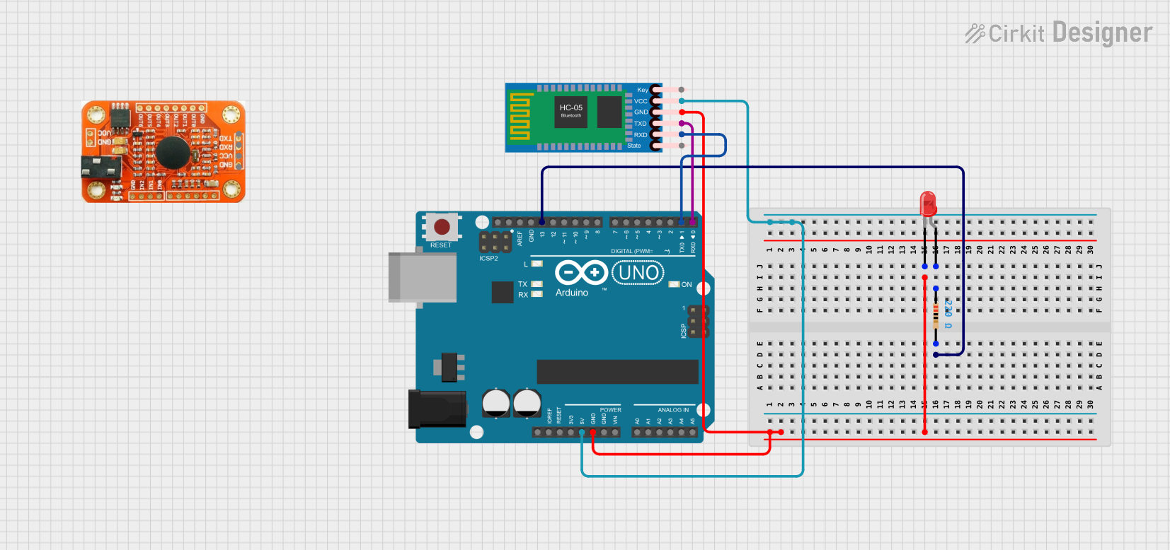
Circuit Documentation
Summary
This circuit integrates an Arduino UNO microcontroller with an HC-05 Bluetooth module, a red LED, and a voice recognition module. The Arduino UNO is programmed to control the LED based on voice commands received through the Bluetooth module. A resistor is used in series with the LED to limit the current.
Component List
Arduino UNO
- Description: A microcontroller board based on the ATmega328P.
- Purpose: Acts as the central processing unit of the circuit, controlling the LED and communicating with the Bluetooth module.
HC-05 Bluetooth Module
- Description: A Bluetooth module for wireless communication.
- Purpose: Receives voice commands from a Bluetooth-enabled device and sends them to the Arduino UNO.
LED: Two Pin (red)
- Description: A basic red light-emitting diode.
- Purpose: Indicates the output status or response to voice commands.
Voice Recognition Module
- Description: A module capable of recognizing voice commands.
- Purpose: Processes voice commands and sends the recognized command to the Arduino UNO.
Resistor (220 Ohms)
- Description: A passive two-terminal electrical component that implements electrical resistance.
- Purpose: Limits the current flowing through the LED to prevent damage.
Wiring Details
Arduino UNO
- GND: Connected to the ground pins of the HC-05 Bluetooth module and the cathode of the LED.
- 5V: Supplies power to the VCC pin of the HC-05 Bluetooth module.
- D13: Connected to one end of the resistor, which is in series with the LED.
- D1 (TX): Connected to the RXD pin of the HC-05 Bluetooth module for serial communication.
- D0 (RX): Connected to the TXD pin of the HC-05 Bluetooth module for serial communication.
HC-05 Bluetooth Module
- GND: Connected to the ground of the Arduino UNO.
- VCC: Powered by the 5V output from the Arduino UNO.
- TXD: Transmits data to the RX pin (D0) of the Arduino UNO.
- RXD: Receives data from the TX pin (D1) of the Arduino UNO.
LED: Two Pin (red)
- Cathode: Connected to the ground of the Arduino UNO.
- Anode: Connected to one end of the resistor.
Resistor (220 Ohms)
- Pin1: Connected to the anode of the LED.
- Pin2: Connected to pin D13 of the Arduino UNO.
Documented Code
// Code for Arduino UNO
int ledPin = 13; // LED connected to digital pin 13
char voiceCommand; // Variable to store the voice command

void setup() {
  pinMode(ledPin, OUTPUT); // Initialize the LED pin as an output
  Serial.begin(9600); // Start serial communication at 9600 baud rate
}

void loop() {
  if (Serial.available() > 0) { // Check if data is available to read
    voiceCommand = Serial.read(); // Read the next character from the serial buffer

    if (voiceCommand == '1') {
      digitalWrite(ledPin, HIGH); // Turn on the LED
    } else if (voiceCommand == '0') {
      digitalWrite(ledPin, LOW); // Turn off the LED
    }
  }
}
This code is designed to run on the Arduino UNO. It initializes the LED pin and sets up serial communication. The loop function checks for incoming serial data, which represents voice commands. If the command '1' is received, the LED is turned on. If '0' is received, the LED is turned off.