Cirkit Designer
Your all-in-one circuit design IDE
Home /
Project Documentation
Arduino UNO Controlled Multi-Color LED Array
Circuit Documentation
Summary
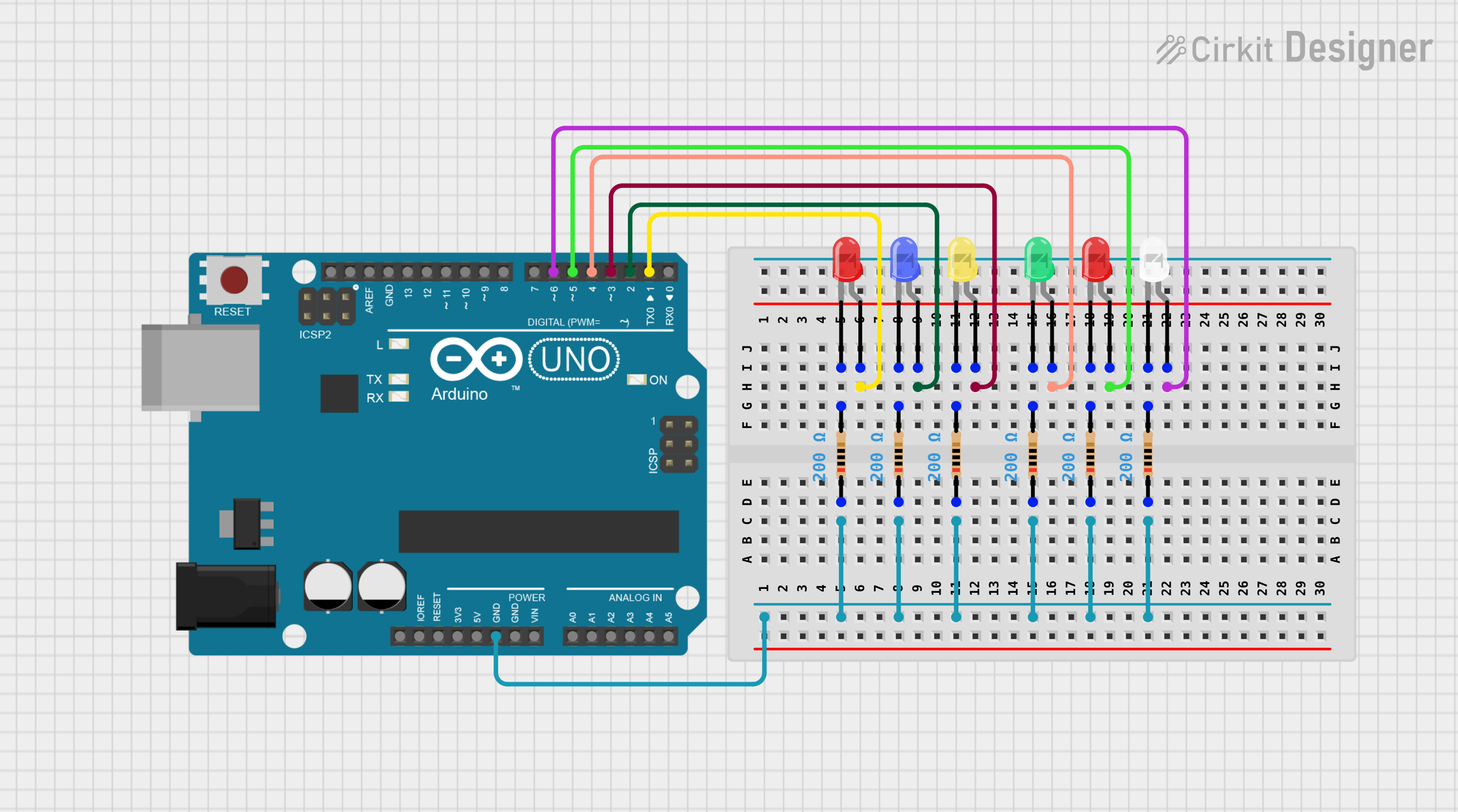
This circuit is designed around an Arduino UNO microcontroller and includes a series of LEDs with corresponding resistors. Each LED is connected to a digital output pin on the Arduino and is protected by a resistor in series. The resistors ensure that the LEDs receive an appropriate amount of current when the corresponding pin is set to a high state. The ground pins of the LEDs are all connected together and then to the ground (GND) pin of the Arduino, forming a common ground.
Component List
Microcontroller
- Arduino UNO: A microcontroller board based on the ATmega328P. It has 14 digital input/output pins, 6 analog inputs, a 16 MHz quartz crystal, a USB connection, a power jack, an ICSP header, and a reset button.
LEDs
- LED (Red): A two-pin red light-emitting diode.
- LED (Blue): A two-pin blue light-emitting diode.
- LED (Yellow): A two-pin yellow light-emitting diode.
- LED (Green): A two-pin green light-emitting diode.
- LED (White): A two-pin white light-emitting diode.
Resistors
- Resistor: A passive two-terminal electrical component with a resistance of 200 Ohms. It is used to limit the current flowing through the LEDs.
Wiring Details
Arduino UNO
- Digital pins D1 to D6 are each connected to the anode of a different colored LED.
- GND pin is connected to the cathodes of all LEDs through their respective resistors.
LEDs
LED (Red)
- Anode: Connected to Arduino UNO digital pin (D1 or D5).
- Cathode: Connected to one end of a 200 Ohm resistor.
LED (Blue)
- Anode: Connected to Arduino UNO digital pin D2.
- Cathode: Connected to one end of a 200 Ohm resistor.
LED (Yellow)
- Anode: Connected to Arduino UNO digital pin D3.
- Cathode: Connected to one end of a 200 Ohm resistor.
LED (Green)
- Anode: Connected to Arduino UNO digital pin D4.
- Cathode: Connected to one end of a 200 Ohm resistor.
LED (White)
- Anode: Connected to Arduino UNO digital pin D6.
- Cathode: Connected to one end of a 200 Ohm resistor.
Resistors
- All resistors have one end connected to the cathode of an LED and the other end connected to the GND pin of the Arduino UNO.
Documented Code
Arduino UNO Code (sketch.ino)
void setup() {
  // put your setup code here, to run once:

}

void loop() {
  // put your main code here, to run repeatedly:

}
Additional Notes
- The provided code is a template and does not contain any functionality. To control the LEDs, the digital pins D1 to D6 should be set as outputs in the
setup()function, and then they can be turned on or off by writing a HIGH or LOW value to them in theloop()function. - The
documentation.txtfile is mentioned but contains no content. Additional documentation or code comments should be added as needed for clarity and maintenance purposes.