
Arduino Nano Controlled IR Sensor with RGB Feedback and Alert System
View and Edit Project In Cirkit Designer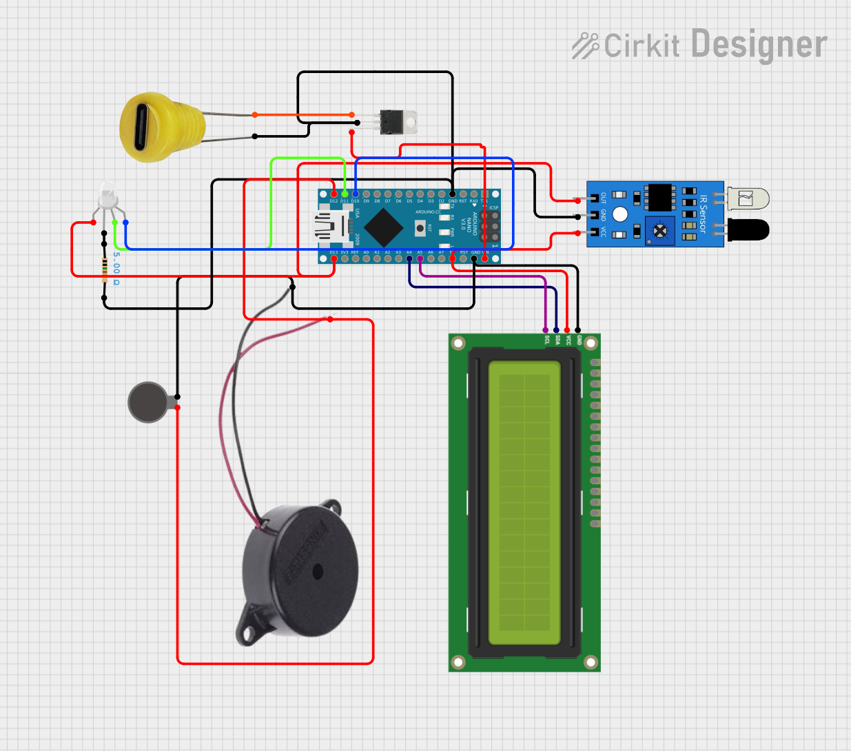
Circuit Documentation
Summary of the Circuit
The circuit in question appears to be a microcontroller-based system designed to interface with an IR sensor, an I2C LCD screen, a vibration motor, a buzzer, an RGB LED, and a voltage regulator. The microcontroller used is an Arduino Nano, which controls the various peripherals and manages input from the IR sensor. The LCD screen is used for displaying information, while the RGB LED, vibration motor, and buzzer serve as output indicators. The LM7805 voltage regulator is used to ensure a stable 5V supply to the components that require it, and a 5V Type C DC socket provides power to the circuit.
Component List
IR Sensor
- Pins: out, gnd, vcc
- Description: An infrared sensor used for detecting objects or motion.
I2C LCD 16x2 Screen
- Pins: SCL, SDA, VCC (5V), GND, VDD, VO, RS, RW, E, D0, D1, D2, D3, D4, D5, D6, D7, BLA, BLK
- Description: A 16x2 character LCD display that communicates over the I2C bus.
Arduino Nano
- Pins: D1/TX, D0/RX, RESET, GND, D2, D3, D4, D5, D6, D7, D8, D9, D10, D11/MOSI, D12/MISO, VIN, 5V, A7, A6, A5, A4, A3, A2, A1, A0, AREF, 3V3, D13/SCK
- Description: A compact microcontroller board based on the ATmega328P, with digital and analog I/O pins.
Vibration Motor
- Pins: +, -
- Description: A small motor that vibrates when powered, often used for haptic feedback.
Buzzer
- Pins: POSITIVE, NEGATIVE
- Description: An electronic buzzer that produces sound when energized.
LM7805 Voltage Regulator
- Pins: IN PIN, OUT PIN, GND
- Description: A voltage regulator that outputs a stable 5V from a higher input voltage.
5V Type C DC Socket
- Pins: - Negative, + Positive
- Description: A power socket for a Type C connector to supply power to the circuit.
RGB LED (Wokwi compatible)
- Pins: R, COM, G, B
- Description: A multicolor LED capable of displaying a range of colors by mixing red, green, and blue.
Resistor
- Pins: pin1, pin2
- Properties: Resistance: 5 Ohms
- Description: A resistor with a resistance of 5 Ohms, likely used for current limiting.
Wiring Details
IR Sensor
- out: Connected to the R pin of the RGB LED and D13/SCK of the Arduino Nano.
- gnd: Connected to the GND pin of the LM7805, - Negative of the 5V Type C DC Socket, and GND of the Arduino Nano through a Resistor.
- vcc: Connected to the VCC (5V) of the I2C LCD Screen and 5V of the Arduino Nano.
I2C LCD 16x2 Screen
- SCL: Connected to A5 of the Arduino Nano.
- SDA: Connected to A4 of the Arduino Nano.
- VCC (5V): Connected to the vcc of the IR Sensor and 5V of the Arduino Nano.
- GND: Connected to the GND of the Vibration Motor, NEGATIVE of the Buzzer, and GND of the Arduino Nano.
Arduino Nano
- D13/SCK: Connected to the out pin of the IR Sensor and R pin of the RGB LED.
- GND: Common ground connected to the gnd pin of the IR Sensor, GND of the LM7805, - Negative of the 5V Type C DC Socket, and GND of the I2C LCD Screen.
- 5V: Connected to the vcc pin of the IR Sensor and VCC (5V) of the I2C LCD Screen.
- A5: Connected to the SCL pin of the I2C LCD Screen.
- A4: Connected to the SDA pin of the I2C LCD Screen.
- D10: Connected to the B pin of the RGB LED.
- D11/MOSI: Connected to the G pin of the RGB LED.
- D12/MISO: Connected to the + pin of the Vibration Motor and POSITIVE of the Buzzer.
- VIN: Connected to the OUT PIN of the LM7805.
Vibration Motor
- +: Connected to D12/MISO of the Arduino Nano.
- -: Connected to the GND of the I2C LCD Screen.
Buzzer
- POSITIVE: Connected to D12/MISO of the Arduino Nano.
- NEGATIVE: Connected to the GND of the I2C LCD Screen.
LM7805 Voltage Regulator
- IN PIN: Connected to the + Positive of the 5V Type C DC Socket.
- OUT PIN: Connected to VIN of the Arduino Nano.
- GND: Connected to the gnd pin of the IR Sensor.
5V Type C DC Socket
-
- Negative: Connected to the gnd pin of the IR Sensor.
-
- Positive: Connected to the IN PIN of the LM7805.
RGB LED (Wokwi compatible)
- R: Connected to the out pin of the IR Sensor and D13/SCK of the Arduino Nano.
- COM: Connected to pin1 of the Resistor.
- G: Connected to D11/MOSI of the Arduino Nano.
- B: Connected to D10 of the Arduino Nano.
Resistor
- pin1: Connected to the COM pin of the RGB LED.
- pin2: Connected to the gnd pin of the IR Sensor.
Documented Code
void setup() {
  // put your setup code here, to run once:

}

void loop() {
  // put your main code here, to run repeatedly:

}
The provided code is a template with empty setup() and loop() functions, which are the standard structure for Arduino sketches. The setup() function is intended to contain initialization code that runs once when the microcontroller is powered on or reset. The loop() function is for code that runs continuously as long as the microcontroller is powered.
Further implementation details would be required to provide a functional sketch that interacts with the connected components.