
ESP32-Controlled Security System with Ultrasonic Sensing and Solenoid Lock
View and Edit Project In Cirkit Designer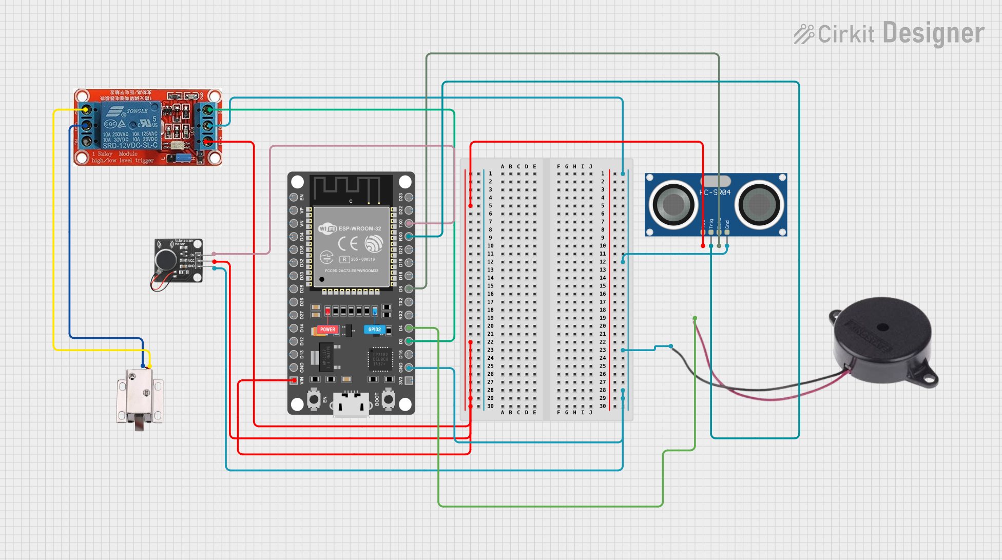
Circuit Documentation
Summary of the Circuit
This circuit is designed to interface an ESP32 microcontroller with a variety of peripherals including a PWM Vibration Motor Sensor Module, an HC-SR04 Ultrasonic Sensor, a 12V solenoid lock, a 12V relay, and a buzzer. The ESP32 controls these components, likely for a system requiring distance measurement, haptic feedback, access control (solenoid lock), and audible alerts (buzzer). The relay is used to control the high-power solenoid lock with the low-power signal from the ESP32. The ESP32's power lines are also connected to the power lines of the other components, indicating a common power supply for the system.
Component List
ESP 32 DEVKIT V1 (30 pins)
- A microcontroller development board based on the ESP32 chip, featuring Wi-Fi and Bluetooth capabilities, along with a range of GPIO pins for interfacing with various sensors and actuators.
12V Solenoid Lock
- An electrically-controlled lock that can be used for access control systems, which operates on 12V.
PWM Vibration Motor Sensor Module Switch
- A module that can drive a vibration motor with a PWM signal, allowing for haptic feedback in a system.
HC-SR04 Ultrasonic Sensor
- A sensor that measures distance by emitting ultrasonic waves and measuring the time taken for the echo to return.
12V Relay
- An electromechanical switch that allows a low-power signal from the microcontroller to control a higher power circuit, such as the solenoid lock.
Buzzer
- An audible signaling device that can produce a tone when powered, used for alerts or notifications.
Wiring Details
ESP 32 DEVKIT V1 (30 pins)
- VIN: Connected to the power supply lines of the PWM Vibration Motor Sensor Module, HC-SR04 Ultrasonic Sensor, and 12V Relay.
- GND: Common ground with the PWM Vibration Motor Sensor Module, HC-SR04 Ultrasonic Sensor, 12V Relay, and Buzzer.
- D2: Controls the IN pin of the 12V Relay.
- D4: Connected to the POSITIVE pin of the Buzzer.
- D5: Connected to the ECHO pin of the HC-SR04 Ultrasonic Sensor.
- RX0: Connected to the TRIG pin of the HC-SR04 Ultrasonic Sensor.
- TX0: Connected to the Signal pin of the PWM Vibration Motor Sensor Module Switch.
12V Solenoid Lock
- VCC: Connected to the NO (Normally Open) pin of the 12V Relay.
- GND: Connected to the COM (Common) pin of the 12V Relay.
PWM Vibration Motor Sensor Module Switch
- Vcc: Powered by the VIN pin of the ESP32.
- Ground: Common ground with the ESP32.
- Signal: Controlled by the TX0 pin of the ESP32.
HC-SR04 Ultrasonic Sensor
- VCC: Powered by the VIN pin of the ESP32.
- TRIG: Triggered by the RX0 pin of the ESP32.
- ECHO: Output connected to the D5 pin of the ESP32.
- GND: Common ground with the ESP32.
12V Relay
- DC+: Powered by the VIN pin of the ESP32.
- DC-: Common ground with the ESP32.
- IN: Controlled by the D2 pin of the ESP32.
- NO: Connected to the VCC pin of the 12V Solenoid Lock.
- COM: Connected to the GND pin of the 12V Solenoid Lock.
Buzzer
- POSITIVE: Connected to the D4 pin of the ESP32.
- NEGATIVE: Common ground with the ESP32.
Documented Code
No code has been provided for the microcontroller. The expected code should initialize the GPIO pins connected to the relay, buzzer, and ultrasonic sensor. It should include routines to measure distance using the ultrasonic sensor, control the solenoid lock via the relay, provide haptic feedback using the vibration motor, and emit sound using the buzzer.