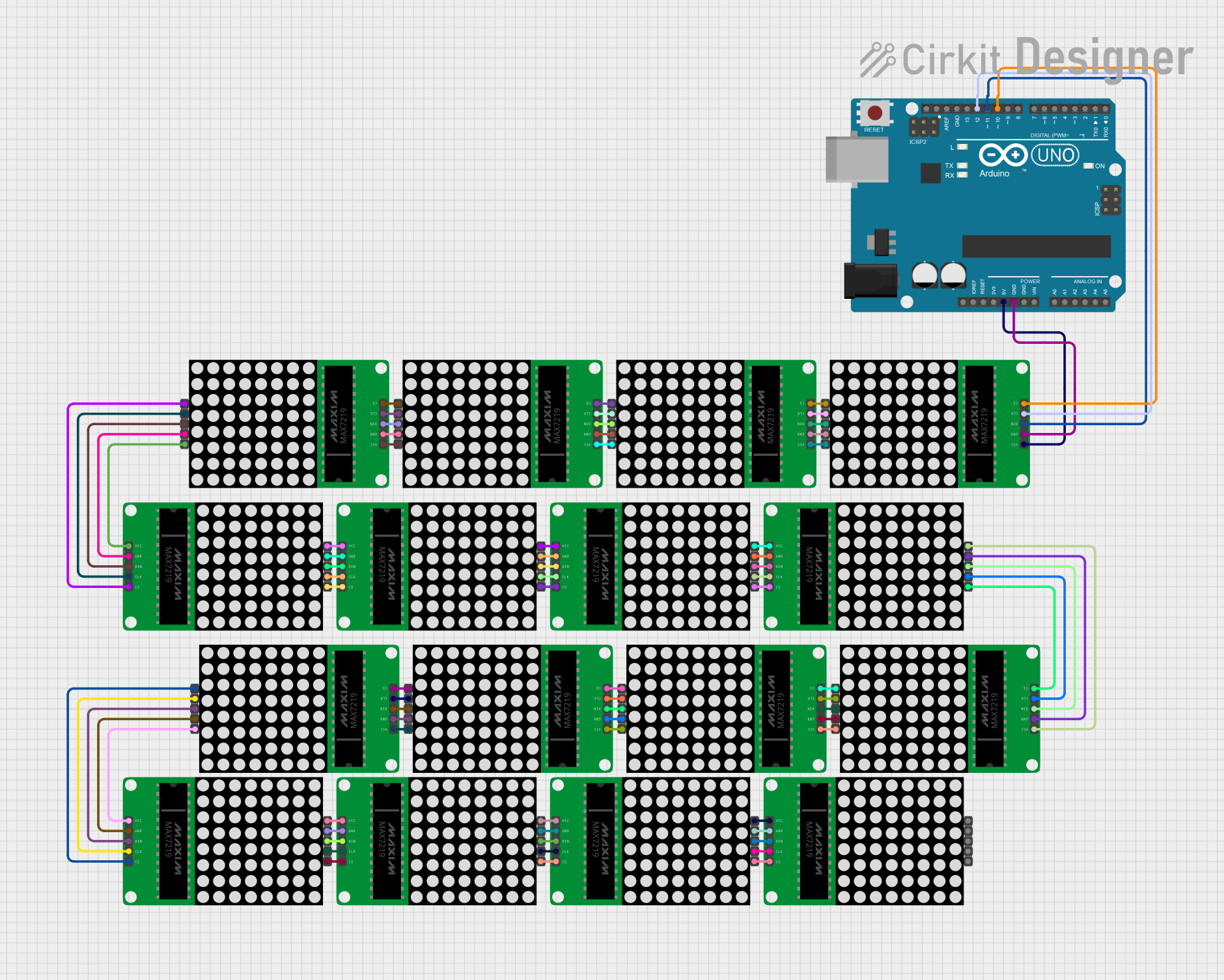
Arduino UNO Controlled Multi-Matrix LED Display

Circuit Documentation
Summary
This circuit consists of an Arduino UNO microcontroller connected to a series of MAX7219 8x8 LED Matrix modules. The Arduino UNO controls the LED matrices using a bit-banged SPI communication protocol. The matrices are daisy-chained together, allowing for control over a large display area using a minimal number of microcontroller pins. The circuit is designed to create visual patterns or display information across the LED matrix array.
Component List
Arduino UNO
- Description: A microcontroller board based on the ATmega328P.
- Pins Used:
5V- Power supply to the LED matrices.GND- Ground reference for the circuit.D12- Clock signal for SPI communication.D11- Data input for SPI communication.D10- Chip select for SPI communication.
MAX7219 8x8 LED Matrix
- Description: An 8x8 LED Matrix controlled by the MAX7219 driver.
- Pins Used:
CS- Chip select, used to enable and disable the device.CLK- Clock input, used to synchronize data transmission.DIN- Serial data input.GND- Ground reference for the matrix.VCC- Power supply for the matrix.CS(OUT),CLK(OUT),DOUT,VCC(OUT)- Used to daisy-chain multiple matrices.
Wiring Details
Arduino UNO
5Vconnected toVCCon the first MAX7219 LED Matrix.GNDconnected toGNDon the first MAX7219 LED Matrix.D12connected toCLKon the first MAX7219 LED Matrix.D11connected toDINon the first MAX7219 LED Matrix.D10connected toCSon the first MAX7219 LED Matrix.
MAX7219 8x8 LED Matrix
VCCconnected to5Vfrom Arduino UNO orVCC(OUT)from the previous matrix in the chain.GNDconnected toGNDfrom Arduino UNO orGNDfrom the previous matrix in the chain.CLKconnected toD12on Arduino UNO orCLK(OUT)from the previous matrix in the chain.DINconnected toD11on Arduino UNO orDOUTfrom the previous matrix in the chain.CSconnected toD10on Arduino UNO orCS(OUT)from the previous matrix in the chain.
Documented Code
// This version uses bit-banged SPI.
// If you see tearing (jagged edges on the circles) try the version
// which uses AVR's hardware SPI peripheral:
// https://wokwi.com/arduino/projects/318868939929027156

#define CLK 12
#define DIN 11
#define CS  10
#define X_SEGMENTS   4
#define Y_SEGMENTS   4
#define NUM_SEGMENTS (X_SEGMENTS * Y_SEGMENTS)

// a framebuffer to hold the state of the entire matrix of LEDs
// laid out in raster order, with (0, 0) at the top-left
byte fb[8 * NUM_SEGMENTS];

void shiftAll(byte send_to_address, byte send_this_data)
{
  digitalWrite(CS, LOW);
  for (int i = 0; i < NUM_SEGMENTS; i++) {
    shiftOut(DIN, CLK, MSBFIRST, send_to_address);
    shiftOut(DIN, CLK, MSBFIRST, send_this_data);
  }
  digitalWrite(CS, HIGH);
}

void setup() {
  Serial.begin(115200);
  pinMode(CLK, OUTPUT);
  pinMode(DIN, OUTPUT);
  pinMode(CS, OUTPUT);

  // Setup each MAX7219
  shiftAll(0x0f, 0x00); //display test register - test mode off
  shiftAll(0x0b, 0x07); //scan limit register - display digits 0 thru 7
  shiftAll(0x0c, 0x01); //shutdown register - normal operation
  shiftAll(0x0a, 0x0f); //intensity register - max brightness
  shiftAll(0x09, 0x00); //decode mode register - No decode
}

void loop() {
  // Animation and display update logic goes here
  // ...
  show();
}

void set_pixel(uint8_t x, uint8_t y, uint8_t mode) {
  // Set, clear, or toggle a pixel in the framebuffer
  // ...
}

void safe_pixel(uint8_t x, uint8_t y, uint8_t mode) {
  // Set a pixel only if it is within the display bounds
  // ...
}

void clear() {
  // Clear the framebuffer
  // ...
}

void show() {
  // Send the framebuffer to the LED matrix
  // ...
}
The provided code initializes and controls a series of daisy-chained MAX7219 8x8 LED Matrix modules. It includes functions for setting individual pixels, clearing the display, and updating the LED matrices with the contents of a framebuffer. The shiftAll function is used to send commands to all connected MAX7219 modules simultaneously. The setup function initializes the matrices, and the loop function contains the logic for updating the display.