Arduino UNO and ESP32-CAM Serial Communication Interface
Circuit Documentation
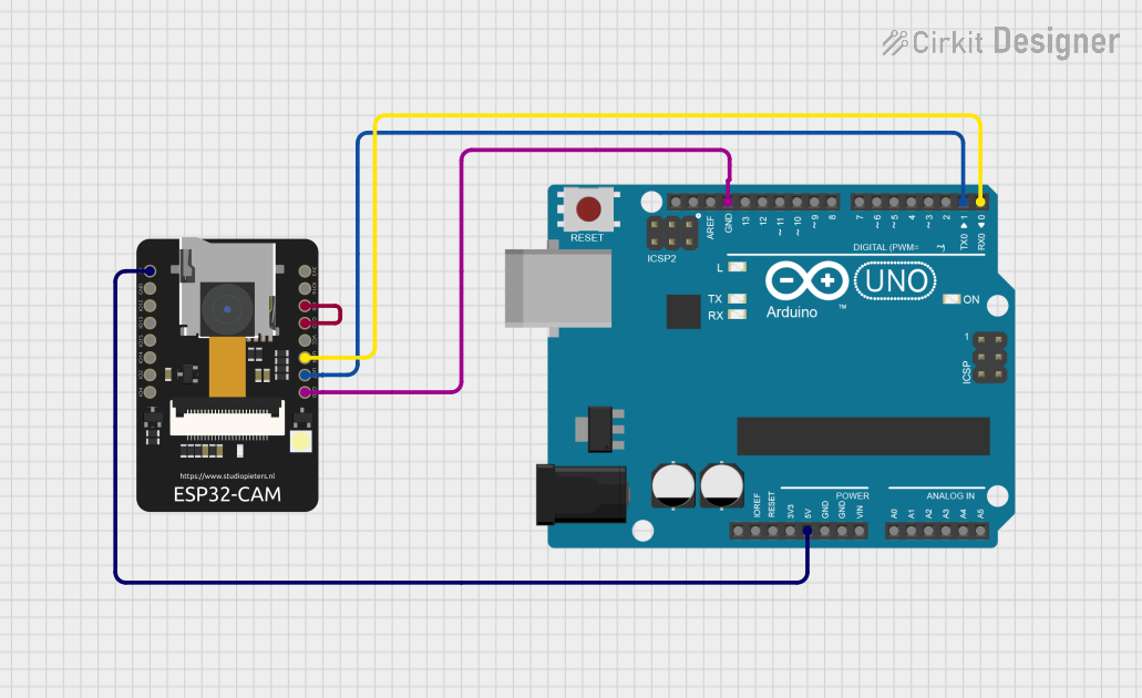
Summary of the Circuit
This circuit consists of two primary components: an Arduino UNO and an ESP32-CAM module. The Arduino UNO serves as the main microcontroller platform, while the ESP32-CAM provides Wi-Fi and Bluetooth capabilities along with camera functionalities. The two components are interconnected for power and serial communication. Additionally, there is a connection on the ESP32-CAM that pulls the IO0 pin to ground, which is typically used for entering the bootloader mode for programming.
Component List
Arduino UNO
- Description: A microcontroller board based on the ATmega328P.
- Pins Used:
5V: Power supply to the board and other components.GND: Ground reference for the circuit.D0: Serial communication (RX).D1: Serial communication (TX).
ESP32 - CAM
- Description: A small-sized ESP32-based module with Wi-Fi, Bluetooth, and a camera interface.
- Pins Used:
5V: Power supply input.GND: Ground reference for the circuit.VOT: Serial communication (TX) connected to Arduino's RX.VOR: Serial communication (RX) connected to Arduino's TX.IO0: General-purpose input/output, connected to GND.
Wiring Details
Arduino UNO
5Vconnected to ESP32 - CAM5VGNDconnected to ESP32 - CAMGNDD0(RX) connected to ESP32 - CAMVORD1(TX) connected to ESP32 - CAMVOT
ESP32 - CAM
5Vconnected to Arduino UNO5VGNDconnected to Arduino UNOGNDand ESP32 - CAMIO0VOTconnected to Arduino UNOD1(TX)VORconnected to Arduino UNOD0(RX)IO0connected toGND(for programming mode)
Documented Code
Arduino UNO Code (sketch.ino)
void setup() {
  // put your setup code here, to run once:

}

void loop() {
  // put your main code here, to run repeatedly:

}
Note: The provided code for the Arduino UNO is a template with empty setup and loop functions. This code needs to be populated with the desired functionality for the circuit to perform its intended tasks.
ESP32 - CAM Code
No code was provided for the ESP32 - CAM module. If the ESP32 - CAM is to be programmed, appropriate code needs to be developed and uploaded to the module.
End of documentation.