Cirkit Designer
Your all-in-one circuit design IDE
Home /
Project Documentation
555 Timer and Relay-Based Water Pump Controller
Circuit Documentation
Summary
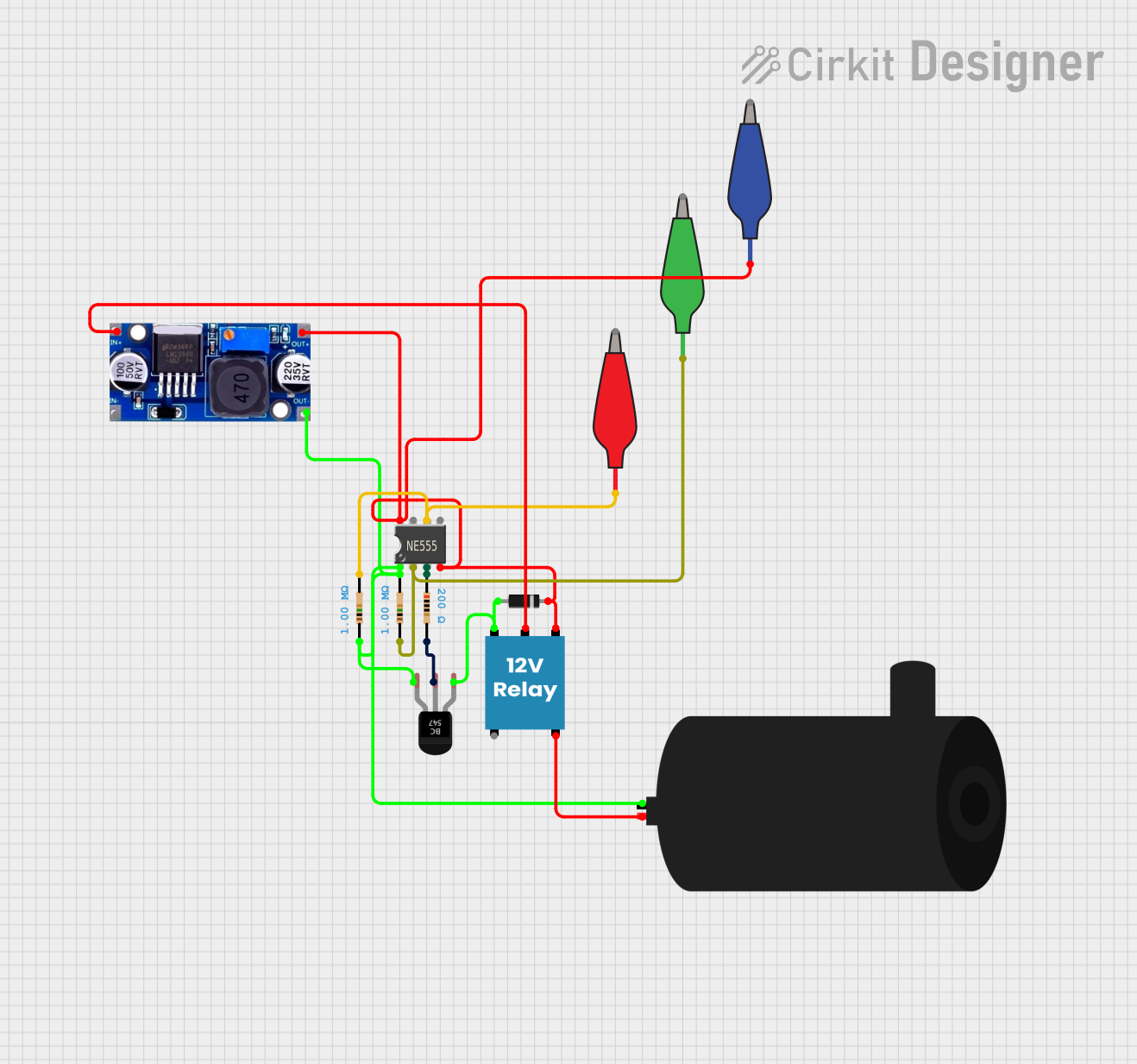
This document provides a detailed overview of a circuit that includes a 555 Timer IC, resistors, a BC547 transistor, a 12V relay, a diode, alligator clip cables, a water pump, and an LM2596 voltage regulator. The circuit is designed to control a water pump using a 555 Timer IC and a relay, with various components interconnected to achieve the desired functionality.
Component List
555 Timer IC
- Description: A versatile timer IC used for generating precise time delays or oscillation.
- Pins: VCC+, Dis, Th, CV, Rst, Out, Trig, GND
Resistor (1M Ohms)
- Description: A resistor with a resistance of 1M Ohms.
- Pins: pin1, pin2
- Properties:
- Resistance: 1M Ohms
Resistor (200 Ohms)
- Description: A resistor with a resistance of 200 Ohms.
- Pins: pin1, pin2
- Properties:
- Resistance: 200 Ohms
BC547 Transistor
- Description: A general-purpose NPN transistor.
- Pins: Collector, Base, Emitter
12V Relay
- Description: An electromechanical switch that uses a 12V signal to control a higher power circuit.
- Pins: +, -, C, NC, NO
Diode
- Description: A semiconductor device that allows current to flow in one direction only.
- Pins: cathode, anode
Alligator Clip Cable (Green)
- Description: A green alligator clip cable used for temporary connections.
- Pins: Pin, Alligator
Alligator Clip Cable (Blue)
- Description: A blue alligator clip cable used for temporary connections.
- Pins: Pin, Alligator
Alligator Clip Cable (Red)
- Description: A red alligator clip cable used for temporary connections.
- Pins: Pin, Alligator
Water Pump
- Description: A pump used to move water.
- Pins: positive, negative
LM2596
- Description: A voltage regulator used to step down voltage.
- Pins: IN, OUT
Wiring Details
555 Timer IC
- VCC+ is connected to:
- Diode (cathode)
- 12V Relay (-)
- Alligator Clip Cable (Blue) (Pin)
- LM2596 (OUT)
- Rst is connected to:
- Diode (cathode)
- 12V Relay (-)
- Alligator Clip Cable (Blue) (Pin)
- LM2596 (OUT)
- Th is connected to:
- Resistor (1M Ohms) (pin2)
- Alligator Clip Cable (Red) (Pin)
- Out is connected to:
- Resistor (200 Ohms) (pin1)
- Trig is connected to:
- Resistor (1M Ohms) (pin1)
- Alligator Clip Cable (Green) (Pin)
- GND is connected to:
- Water Pump (negative)
- Resistor (1M Ohms) (pin1)
- BC547 Transistor (Emitter)
- Resistor (1M Ohms) (pin2)
- LM2596 (OUT)
Resistor (1M Ohms)
- pin1 is connected to:
- 555 Timer IC (Trig)
- Alligator Clip Cable (Green) (Pin)
- Water Pump (negative)
- 555 Timer IC (GND)
- pin2 is connected to:
- 555 Timer IC (Th)
- Alligator Clip Cable (Red) (Pin)
- BC547 Transistor (Emitter)
- LM2596 (OUT)
Resistor (200 Ohms)
- pin1 is connected to:
- 555 Timer IC (Out)
- pin2 is connected to:
- BC547 Transistor (Base)
BC547 Transistor
- Collector is connected to:
- Diode (anode)
- 12V Relay (+)
- Base is connected to:
- Resistor (200 Ohms) (pin2)
- Emitter is connected to:
- Water Pump (negative)
- Resistor (1M Ohms) (pin1)
- 555 Timer IC (GND)
- Resistor (1M Ohms) (pin2)
- LM2596 (OUT)
12V Relay
- + is connected to:
- Diode (anode)
- BC547 Transistor (Collector)
- - is connected to:
- Diode (cathode)
- 555 Timer IC (VCC+)
- 555 Timer IC (Rst)
- Alligator Clip Cable (Blue) (Pin)
- LM2596 (OUT)
- C is connected to:
- LM2596 (IN)
- NO is connected to:
- Water Pump (positive)
Diode
- cathode is connected to:
- 12V Relay (-)
- 555 Timer IC (VCC+)
- 555 Timer IC (Rst)
- Alligator Clip Cable (Blue) (Pin)
- LM2596 (OUT)
- anode is connected to:
- 12V Relay (+)
- BC547 Transistor (Collector)
Alligator Clip Cable (Green)
- Pin is connected to:
- 555 Timer IC (Trig)
- Resistor (1M Ohms) (pin1)
Alligator Clip Cable (Blue)
- Pin is connected to:
- Diode (cathode)
- 12V Relay (-)
- 555 Timer IC (VCC+)
- 555 Timer IC (Rst)
- LM2596 (OUT)
Alligator Clip Cable (Red)
- Pin is connected to:
- Resistor (1M Ohms) (pin2)
- 555 Timer IC (Th)
Water Pump
- positive is connected to:
- 12V Relay (NO)
- negative is connected to:
- Resistor (1M Ohms) (pin1)
- 555 Timer IC (GND)
- BC547 Transistor (Emitter)
- Resistor (1M Ohms) (pin2)
- LM2596 (OUT)
LM2596
- IN is connected to:
- 12V Relay (C)
- OUT is connected to:
- Diode (cathode)
- 12V Relay (-)
- 555 Timer IC (VCC+)
- 555 Timer IC (Rst)
- Alligator Clip Cable (Blue) (Pin)
- 555 Timer IC (GND)
- Water Pump (negative)
- Resistor (1M Ohms) (pin1)
- BC547 Transistor (Emitter)
- Resistor (1M Ohms) (pin2)
Code
There is no code provided for this circuit.