
Circuit Documentation
Summary
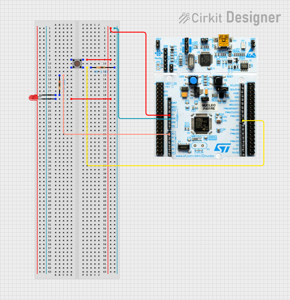
This circuit consists of a Nucleo 401RE microcontroller, a pushbutton, a red LED, and two resistors. The pushbutton is used to toggle the state of the LED. The LED is connected to an analog pin (A0) of the microcontroller, and the pushbutton is connected to a digital pin (D8). The circuit includes resistors to limit current and ensure proper operation.
Component List
Nucleo 401RE
- Description: Microcontroller board based on the STM32F401RE.
- Pins: IOREF, NRST, 3V3, 5V, GND, VIN, A0, A1, A2, A3, A4, A5, D0, D1, D2, D3, D4, D5, D6, D7, D8, D9, D10, D11, D12, D13, AVD0, D14, D15
Pushbutton
- Description: A simple pushbutton switch.
- Pins: Pin 3 (out), Pin 4 (out), Pin 1 (in), Pin 2 (in)
Resistor (10k Ohms)
- Description: Resistor with a resistance of 10k Ohms.
- Pins: pin1, pin2
LED: Two Pin (red)
- Description: A red LED with two pins.
- Pins: cathode, anode
Resistor (200 Ohms)
- Description: Resistor with a resistance of 200 Ohms.
- Pins: pin1, pin2
Wiring Details
Nucleo 401RE
5V is connected to:
- Pushbutton Pin 1 (in)
- LED cathode
D8 is connected to:
- Resistor (10k Ohms) pin2
- Pushbutton Pin 3 (out)
A0 is connected to:
- Resistor (200 Ohms) pin1
GND is connected to:
- Resistor (10k Ohms) pin1
Pushbutton
Pin 1 (in) is connected to:
- Nucleo 401RE 5V
- LED cathode
Pin 3 (out) is connected to:
- Resistor (10k Ohms) pin2
- Nucleo 401RE D8
Resistor (10k Ohms)
pin1 is connected to:
- Nucleo 401RE GND
pin2 is connected to:
- Pushbutton Pin 3 (out)
- Nucleo 401RE D8
LED: Two Pin (red)
cathode is connected to:
- Pushbutton Pin 1 (in)
- Nucleo 401RE 5V
anode is connected to:
- Resistor (200 Ohms) pin2
Resistor (200 Ohms)
pin1 is connected to:
- Nucleo 401RE A0
pin2 is connected to:
- LED anode
Code Documentation
/*
 * This Arduino sketch is for a circuit where a button is connected to pin PA9
 * (D8) and an LED is connected to pin PA0 (A0). The LED toggles its state on
 * the falling edge of the button press.
 */

const int buttonPin = 8; // PA9 (D8)
const int ledPin = A0;   // PA0 (A0)

bool ledState = LOW;
bool lastButtonState = HIGH;

void setup() {
  pinMode(buttonPin, INPUT_PULLUP); // Set button pin as input with internal pull-up
  pinMode(ledPin, OUTPUT);          // Set LED pin as output
  digitalWrite(ledPin, ledState);   // Initialize LED state
}

void loop() {
  bool currentButtonState = digitalRead(buttonPin);

  // Check for falling edge
  if (lastButtonState == HIGH && currentButtonState == LOW) {
    ledState = !ledState;           // Toggle LED state
    digitalWrite(ledPin, ledState); // Update LED
  }

  lastButtonState = currentButtonState; // Update last button state
  delay(50); // Debounce delay
}
This code initializes the button pin as an input with an internal pull-up resistor and the LED pin as an output. In the main loop, it checks for a falling edge on the button press to toggle the LED state. A debounce delay is included to ensure reliable button presses.