
Arduino 101 Controlled Distance Measurement and Display with VL53L1X and I2C LCD
View and Edit Project In Cirkit Designer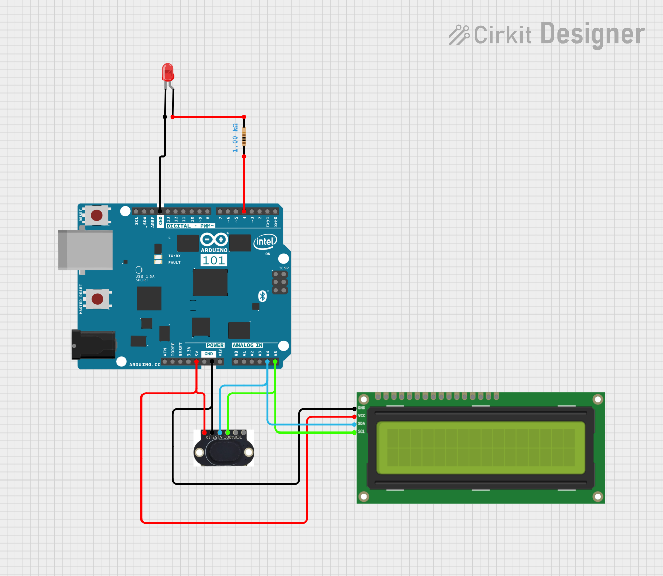
Circuit Documentation
Summary
The circuit in question is designed to interface an Arduino 101 microcontroller with a VL53L1X time-of-flight distance sensor, an I2C LCD 16x2 screen, a red LED, and a resistor. The Arduino 101 serves as the central processing unit, controlling the LED and communicating with both the distance sensor and the LCD via the I2C protocol. The LED is connected to the Arduino with a current-limiting resistor to indicate status or provide user feedback.
Component List
VL53L1X Time-of-Flight Distance Sensor
- Pins: VIN, GND, SDA, SCL, INT, SHUT
- Description: A laser-ranging module that measures accurate distance readings.
Arduino 101
- Pins: A5/SCL, A4/SDA, AREF, GND, D13/SCK, D12/MISO, D11 PWM/MOSI, D10 PWM/SS, D9 PWM, D8, D7, D6 PWM, D5 PWM, D4, D3 PWM, D2, D1/TX, D0/RX, AIN, ioref, RESET, 3V3, 5V, VIN, A0, A1, A2, A3, ICSP MISO, ICSP SCK, ICSP MOSI
- Description: A microcontroller board based on the Intel Curie module, suitable for building IoT applications.
Resistor (1 kOhm)
- Pins: pin1, pin2
- Description: A passive two-terminal electrical component that implements electrical resistance as a circuit element.
LED: Two Pin (red)
- Pins: cathode, anode
- Description: A red light-emitting diode used for indication purposes.
I2C LCD 16x2 Screen
- Pins: SCL, SDA, VCC (5V), GND, VDD, VO, RS, RW, E, D0, D1, D2, D3, D4, D5, D6, D7, BLA, BLK
- Description: A 16x2 character LCD display that uses the I2C communication protocol.
Wiring Details
VL53L1X Time-of-Flight Distance Sensor
- VIN: Connected to the 5V output from the Arduino 101.
- GND: Connected to the ground (GND) on the Arduino 101.
- SDA: Connected to the SDA (A4) pin on the Arduino 101 for I2C data.
- SCL: Connected to the SCL (A5) pin on the Arduino 101 for I2C clock.
Arduino 101
- 5V: Provides power to the VL53L1X sensor and the I2C LCD screen.
- GND: Common ground for the VL53L1X sensor, I2C LCD screen, and LED.
- A4/SDA: I2C data line connected to the VL53L1X sensor and I2C LCD screen.
- A5/SCL: I2C clock line connected to the VL53L1X sensor and I2C LCD screen.
- D4: Connected to one end of the resistor, which is in series with the LED.
Resistor (1 kOhm)
- pin1: Connected to the D4 pin on the Arduino 101.
- pin2: Connected to the anode of the red LED.
LED: Two Pin (red)
- cathode: Connected to the ground (GND) on the Arduino 101.
- anode: Connected to pin2 of the resistor.
I2C LCD 16x2 Screen
- SCL: Connected to the SCL (A5) pin on the Arduino 101 for I2C clock.
- SDA: Connected to the SDA (A4) pin on the Arduino 101 for I2C data.
- VCC (5V): Connected to the 5V output from the Arduino 101.
- GND: Connected to the ground (GND) on the Arduino 101.
Documented Code
No code has been provided for the microcontroller. The documentation of the code would typically include a description of the functionality, setup, and main loop, along with any functions or libraries used to control the components in the circuit. Since no code is available, this section cannot be completed.