
ESP32-Based Automated Payment Kiosk with Coin Acceptance and Motor Control
View and Edit Project In Cirkit Designer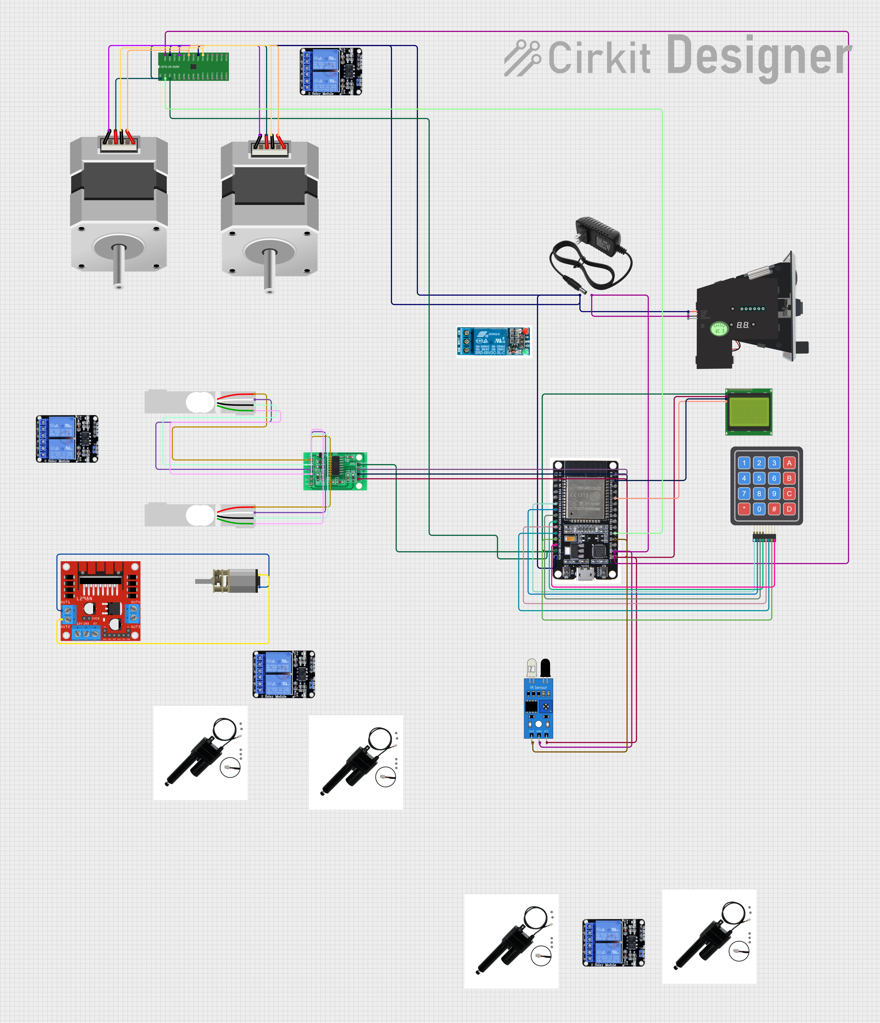
Circuit Documentation
Summary
The circuit in question is designed to interface an ESP32 microcontroller with a variety of peripherals including a 4x4 keypad, an LCD display with I2C interface, a multi-coin acceptor, stepper motors (NEMA23), load cells, linear actuators, a DC mini metal gear motor, an IR sensor, a stepper motor driver (A4983), a DC motor driver (L298N), a bridge sensor interface (HX711), and several relay modules. The ESP32 serves as the central processing unit, handling inputs from the keypad and IR sensor, driving the display, controlling the motors through the drivers, and acquiring data from the load cells via the HX711. The circuit is powered by a 12V power supply, with voltage regulation provided for the various components that require different voltage levels.
Component List
ESP32
- Microcontroller with a variety of digital I/O pins, analog inputs, and communication interfaces such as I2C and UART.
Lcd 20x4 i2c
- An alphanumeric liquid crystal display with 20 characters per line and 4 lines, interfaced via the I2C protocol.
4x4 Keypad (Sim)
- A simulated 4x4 matrix keypad with rows and columns for user input.
12v Power Supply
- Provides a 12V power source for the circuit.
Multi Coin Acceptor
- Accepts multiple types of coins and provides output signals corresponding to the coin inserted.
NEMA23 Stepper Motors
- Two stepper motors used for precise motion control.
Load Cells (Red/white/black/green)
- Two load cells used for measuring weight or force.
Linear Actuators
- Four linear actuators with built-in potentiometers for position feedback.
DC Mini Metal Gear Motor
- A small DC motor with a gearbox for increased torque.
IR Sensor
- An infrared sensor used for object detection or distance measurement.
A4983 Stepper Motor Driver
- A driver module for controlling stepper motors.
L298N DC Motor Driver
- A driver module for controlling DC motors.
HX711 - Bridge Sensor Interface
- An ADC converter and amplifier specifically designed for bridge sensors like load cells.
5v Relay
- A single-channel relay module for switching high-power devices.
Two Channel Relay 5v
- A dual-channel relay module for controlling two separate high-power devices.
Wiring Details
ESP32
- D32 connected to 4x4 Keypad R1
- D33 connected to 4x4 Keypad R2
- D25 connected to 4x4 Keypad R3
- D26 connected to 4x4 Keypad R4
- D27 connected to 4x4 Keypad C1
- D14 connected to 4x4 Keypad C2
- D12 connected to 4x4 Keypad C3
- D13 connected to 4x4 Keypad C4
- GND connected to GND of HX711, A4983, LCD, IR Sensor, and Multi Coin Acceptor
- VIN connected to VBB1 and VBB2 of A4983, and + of 12v Power Supply
- 3V3 connected to 3.3/3.5V Supply of HX711, 5v of LCD, and vcc of IR Sensor
- D2 connected to out of IR Sensor
- D4 connected to ENABLE of A4983
- D21 connected to SCA of LCD
- D22 connected to SCK of HX711 and SCL of LCD
- D23 connected to DATA of HX711
Lcd 20x4 i2c
- GND connected to GND of ESP32
- 5v connected to 3V3 of ESP32
- SCA connected to D21 of ESP32
- SCL connected to D22 of ESP32
4x4 Keypad (Sim)
- R1 connected to D32 of ESP32
- R2 connected to D33 of ESP32
- R3 connected to D25 of ESP32
- R4 connected to D26 of ESP32
- C1 connected to D27 of ESP32
- C2 connected to D14 of ESP32
- C3 connected to D12 of ESP32
- C4 connected to D13 of ESP32
12v Power Supply
-
- connected to VIN of ESP32, DC12V of Multi Coin Acceptor
-
- connected to GND of ESP32, GND of Multi Coin Acceptor
Multi Coin Acceptor
- COIN not connected
- DC12V connected to + of 12v Power Supply
- GND connected to GND of ESP32
- COUNTER not connected
NEMA23 Stepper Motors
- D, B, C, A of both motors connected to OUT2A, OUT2B, OUT1B, OUT1A of A4983 respectively
Load Cells (Red/white/black/green)
- E+, A-, E-, A+ of both cells connected to E+, A-, E-, A+ of HX711 respectively
Linear Actuators
- Wiring details not provided
DC Mini Metal Gear Motor
- IN1 connected to OUT1 of L298N DC motor driver
- IN2 connected to OUT2 of L298N DC motor driver
IR Sensor
- out connected to D2 of ESP32
- gnd connected to GND of ESP32
- vcc connected to 3V3 of ESP32
A4983 Stepper Motor Driver
- ENABLE connected to D4 of ESP32
- GND connected to GND of ESP32
- VBB1 and VBB2 connected to VIN of ESP32
- OUT2A, OUT2B, OUT1B, OUT1A connected to D, B, C, A of NEMA23 motors respectively
L298N DC Motor Driver
- OUT1 connected to IN1 of DC Mini Metal Gear Motor
- OUT2 connected to IN2 of DC Mini Metal Gear Motor
HX711 - Bridge Sensor Interface
- GND connected to GND of ESP32
- 3.3/3.5V Supply connected to 3V3 of ESP32
- SCK connected to D22 of ESP32
- DATA connected to D23 of ESP32
- E+, A-, E-, A+ connected to corresponding pins of Load Cells
5v Relay
- Wiring details not provided
Two Channel Relay 5v
- Wiring details not provided
Documented Code
No code has been provided for the microcontrollers in the circuit. Therefore, this section is currently empty. When code is available, it should be documented here with explanations of its functionality and how it interacts with the connected hardware components.